Attaching the tow beam and hitch plate – DR Power 8 FPT User Manual
Page 10
10
DR
®
CHIPPER/SHREDDER
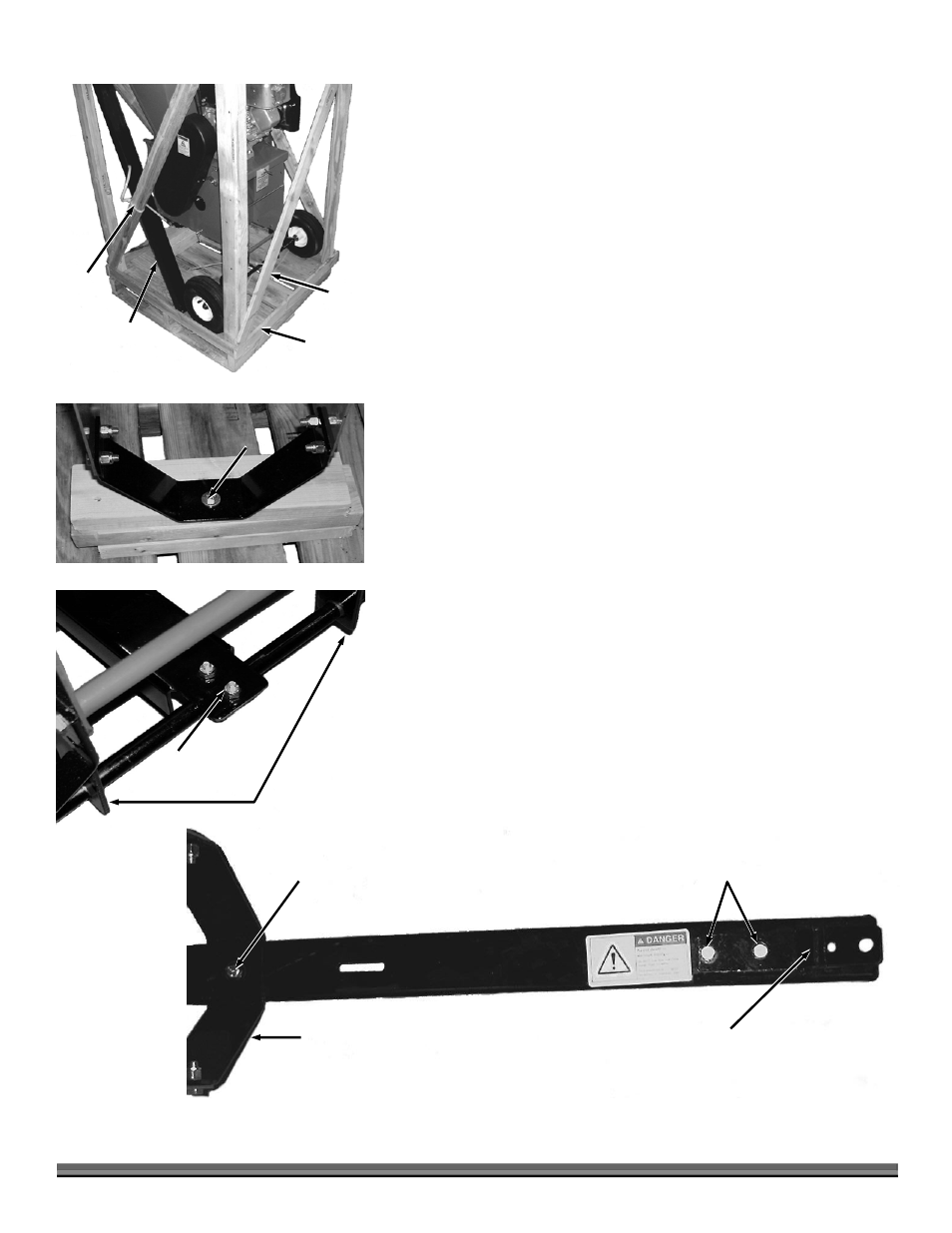
Figure 6
Frame Support
5/16" Bolt
5/16" Bolts
Bent Hitch
Plate
Tow Beam
3. Remove the Tow Beam and lift the Crate off of the Shipping Pallet.
4. Remove the Hardware Plastic Bag, the Chipper Hopper, and the packing
material from inside the Shredder Hopper.
5. Using a 1/2" Wrench, remove the Lag Bolt and Washer securing the front
of the Chipper/Shredder frame to Shipping Pallet (Figure 4). This Bolt and
Washer may be discarded.
6. With the help of another person, carefully roll the DR
CHIPPER/SHREDDER from the Shipping Pallet, resting it on the front
frame support.
7. Compare the contents on the Shipping Pallet and in the Plastic Bag with
the parts supplied list on the previous page. If any of the parts are missing,
contact 1-800-DR-OWNER (376-9637). You will need packaging to return
the machine; do not discard your packaging material until you are fully
satisfied with your new DR CHIPPER/SHREDDER.
Attaching the Tow Beam and Hitch Plate
Tools Needed:
7/16" Wrench
Two 1/2" Wrenches
1. Place the Tow Beam on top of and in the center of the Axle between the
Axle Supports. Put the U-Bolt around the Axle from underneath and up
through the two holes on the Tow Beam (Figure 5). Install two 1/4"- 20
Lock Nuts on the U-Bolt with a7/16" Wrench but do not tighten.
2. Lift the machine and align the Hole the Tow Beam with the Hole in the
Front Frame Support and insert a 5/16"- 18 x 1" Bolt down through the
Frame and through the Tow Beam (Figure 6).
3. With this Bolt in place, block up the Tow Beam so that you can easily install
a 5/16" Flat Washer and a 5/16" - 18 Lock Nut on the Bolt from under the
Tow Beam; but do not tighten.
4. Re-check the center of the Tow Beam on the Axle and tighten the two Lock
Nuts on the U-Bolt.
5. Now tighten the 5/16"-18 Lock Nut to secure the Front Frame Support to
the Tow Beam with two 1/2" Wrenches.
6. Attach the Hitch Plate to the Tow Beam with two 5/16"- 18 x 1" Bolts and
two 5/16"-18 Lock Nuts (Figure 6). Tighten with two 1/2" Wrenches.
Figure 4
Securing
Bolt
Figure 5
Axle Supports
Tow Beam
U-Bolt
Figure 3
Cable
Tie
Cable
Tie
Bottom
Board
(4 places)
Tow Beam