Removing and replacing the clutch – DR Power 8 FPT User Manual
Page 23
CONTACT US AT www.DRpower.com 23
9. Slide the Rod back through the Access Hole and reinstall the Hammers and
Spacers in the same order as removed.
NOTE: Be sure you reinstall the Hammers and Spacers in exactly the same order
that they were removed. Refer to the Rotor Assembly Schematic on page 29 for the
correct order.
10. Replace the old Groove Pin with a new one (deep grooves pointing up to
install).
11. Repeat steps 4 through 10 for the remaining three (3) Hammer(s) Rods.
Tip: To remember which Hammer(s) Rod you have reworked, it may be helpful
to mark the end of the Rods with a marker or tape.
12. Reinstall the Shredder Hopper, Access Cover Plate, Belt Guard, and the Baffle
Plate.
NOTE: When reinstalling the Shredder Hopper Bolts in the Vibration Dampers,
remember that the shorter Bolts are in the Front and the Longer Bolts are in the Rear.
Thread the Bolts up into the Dampers until one (1) or two (2) threads appear.
Thread a Lock Nut onto each of the Bolts coming up through the Vibration Dampers.
Hold the Nut and tighten the Bolt until one (1) thread is completely through the
front Nuts and about (3) threads showing through the Nuts in the rear. DO NOT over tighten the Bolts, as this will damage the
Vibration Dampers and possibly lead to damage to your machine.
Removing and Replacing the Clutch
The design of the Clutch on your machine is for rugged, dependable service, however, it is important to understand the limitations
of a Clutch. The Clutch design is to provide load free starting of the Engine, and slippage under excessive overloading of the
driven application. These features help protect the Engine from damages such as broken crankshafts and starters. The Clutch on
this machine is permanently lubricated and does not require oil or grease. The Drum, Shoes, and Springs in the Clutch are
normal wear items. If, after long periods of use, the Drum wobbles excessively, or if you notice decreased performance of the
Clutch, replace the Clutch.
The Clutch obtains its power from the Engine RPM. The lower the engagement speed, and the higher the maintained Engine
speed, the more torque the Clutch can transfer to the driven unit. NEVER operate the DR CHIPPER/SHREDDER Engine at less
than full RPM.
Tools and Supplies Needed:
(2) 1/2" Wrench
9/16" Wrench
Anti-seize compound
1. Remove the Baffle Plate (page 16), the Belt Guard (page 18), loosen the
Engine Bolts (page 18), and remove the Belt
(page 18) and set it aside.
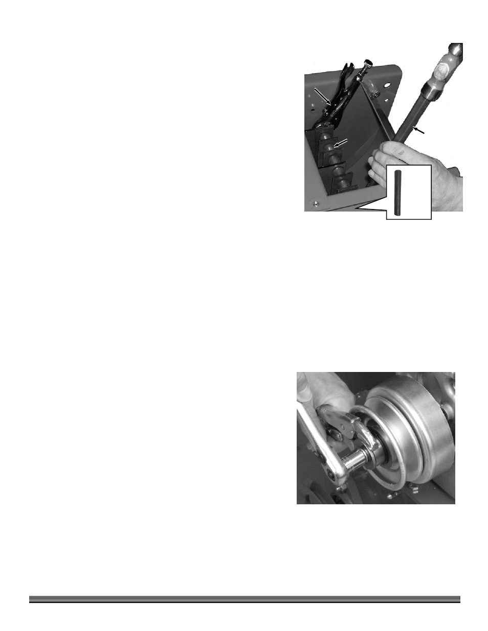
2. Remove the Clutch from the Engine Crankshaft by removing the Clutch Bolt
and Washer and then slide the Clutch Assembly from the Crankshaft (any
Spacer(s) remain on the Crankshaft).
Tip: Hold the Hub with Vise Grips while loosening the Clutch Bolt (Figure 29).
3. Remove the Key from the Keyway in the Engine Crankshaft and set it aside.
4. Clean the Engine Crankshaft and remove any burrs, then apply anti-seize
compound to the Crankshaft.
5. Install the Key in the Keyway of the Engine Crankshaft, align the Key with the slot in the new Clutch Hub, and then slide the
new Clutch Assembly onto the Crankshaft followed by the Washer and Clutch Bolt. Tighten the Bolt securely.
6. Reinstall the Drive Belt and set the Belt tension and alignment (page 18).
7. Reinstall the Belt Guard and Baffle Plate.
Figure 28
Vise Grips
Punch
Hammer(s)
Rod
Deep
Grooves
pointing
down
Figure 29