Control connections, Rs‐485 (4‐wire), Rs‐485 (2‐wire) – FiberPlex TD-7280 User Manual
Page 13
Detailed electrical specifications of the interface can be found in the specification table at the end of the
manual.
RS‐485 (4‐wire)
With ‘Serial Mode’ setting on the Configuration Switch set to ‘on, off’, RS‐485 (4‐wire) mode is enabled. In this
mode, balanced physical connection are made on Interface Connector Pins 7&8 (RX) and 19&20 (TX) with
serial ground reference on Pins 9&21. This is a standard RS‐485 interface with a maximum data rate of 1
Mbps. Depending on the configuration of the third party equipment connected, the definition of the Idle State
of the line may need to be set. This is accomplished using the ‘Idle’ switch of the Configuration Switch
(position 7). With this switch in the disabled state, the idle state of the line will be a ‘0’, when enabled, idle line
state is a ‘1’. Detailed electrical specifications of the interface can be found in the specification table at the
end of the manual.
RS‐485 (2‐wire)
With ‘Serial Mode’ setting on the Configuration Switch set to ‘on, on’, RS‐485 (2‐wire) mode is enabled. In this
mode, balanced physical connection are made on Interface Connector Pins 19&20 (RX/TX) only with serial
ground reference on Pin 21. This is a standard RS‐485 (2‐wire) interface with a maximum data rate of 1 Mbps.
Depending on the configuration of the third party equipment connected, the definition of the Idle State of the
line may need to be set. This is accomplished using the ‘Idle’ switch of the Configuration Switch (position 7).
With this switch in the disabled state, the idle state of the line will be a ‘0’, when enabled, idle line state is a
‘1’. Detailed electrical specifications of the interface can be found in the specification table at the end of the
manual.
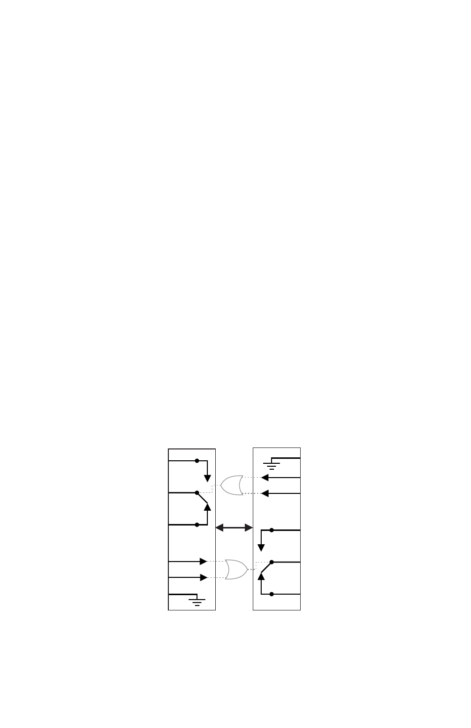
Control Connections
Bi‐directional control capabilities are available on interface connector pins 10‐12 and 22‐24. There are two
types of control activation inputs and a single pole double throw relay output. Pin 11 is a shorting control
input, when this pin is shorted to ground (Pin 10) the relay on the mating FOI(TD)‐7280, on the remote side of
the fiber link, is activated. Likewise, applying a negative DC voltage in the range of ‐6 to ‐48 VDC to Pin 12 will
activate the remote relay. These inputs are ORed meaning that if either one or both are activated, the remote
relay is activated.
The relay pins are found on Pins 22‐24 with Pin 22 being the common connection, Pin 23 being a Normally
Open (NO) connection with respect to the common pin, and Pin 24 being a Normally Closed (NC) connections
with respect to the common pin. An activation on the remotely connected unit will cause these Normal states
to reverse; Pin 23 shorts with Pin 22 and the Normal connection between Pin 24 and Pin 22 is broken. These
states remain reversed as long as the activation pin on the remote unit is enabled. When the activation is
release, they return to their Normal state.
PTT
The ‘PTT’ DIP switch 2 must be enabled for Push‐To‐Talk functionality. This setting mutes the audio inputs. To
activate the PTT operation, apply a negative voltage to pin 12 or ground pin 11 by shorting pin 10 and 11
together on the interface connector. This will actuate the relay in the FOI(TD)‐7280 at the far end causing pins
22 and 23 to close and pins 22 and 24 to open, and also enables the local transmission of the audio inputs.
FOI(TD)-7280
FOI(TD)-7280
23
Normally Open (NO)
Normally Open (NO)
Normally Closed (NC)
Normally Closed (NC)
Common (C)
Common (C)
Negative Voltage Activation(-V)
Negative Voltage Activation(-V)
Shorting Activation(S)
Shorting Activation(S)
Control Ground
Control Ground
22
24
10
11
12
24
22
23
10
12
11
Fiber