Rear indicators/connections, Power requirements and mounting – FiberPlex TD-7280 User Manual
Page 8
Status – LED which indicates the health status of the unit. The LED can be interpreted according to the
following table.
Status Indicator
Off
If Power LED is on, there is an internal failure inside the FOI. Replace
Green
Power supply is operating properly
Amber
At limit of normal range of temperature, apply more cooling to the unit
Red
Exceeding temperature limits or internal failure
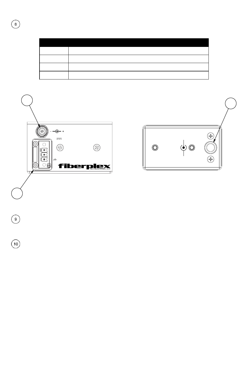
Rear Indicators/Connections
Figure 2 TD‐7280 (left) and FOI‐7280 (right) Rear Face
Circular DC Power Connection – DC power entry for the unit. On the FOI‐7280 this is a LEMO™ connector
designed to interface with either a PSQ power module or RMC chassis. On the TD‐7280 this is a standard DC
connection for use with the included DC wall power supply.
Phoenix™ Power Connection – Secondary power option for the TD‐7280. This is wired in direct parallel
with the Circular connector and has the addition of a positive earth chassis ground connection. This can be
used to power the unit on a client supplied power buss.
Power Requirements and Mounting
Flexible mounting allows the FOI‐7280 to be chassis mounted or standalone configuration. Any combination of
8 FiberPlex FOI units can be mounted in a RMC‐3101 using CMA‐2001 chassis mount adapters. The RMC‐3101
can accommodate hot swapped redundant power. Alternately, the FOI‐7280 can be used in a standalone
application when paired with a PSQ‐4909 for full range AC operation or the PSQ‐4920 for 12‐48VDC operation
Complementing the flexibility of the FiberPlex ‘TD Series’ of fiber optic modules, the TDR‐01‐AC provides
mounting, power and cable management for up to 6 modules in a compact and rugged aluminum 1U rack. The
integrated key‐hole mounting holes on the bottom the TD units lock securely on mating studs while a rear
retention bar holds them securely in place. A 6 position wiring harness and included power adapter provide,
not just 9 VDC power, but a positive earth ground to the modules via 3 position Phoenix™ locking power
connectors. Managing all that cabling and fiber can sometimes be quite a chore so an extended cabling tray
with integrated tie down points are provided to help make your installation clean.
Made in the
USA
V+
V-
7-12 VDC @ 1A
9
10
9
9
-12 VD
C
+
-