Unit 1 unit 2 unit n – FiberPlex TD-7280 User Manual
Page 15
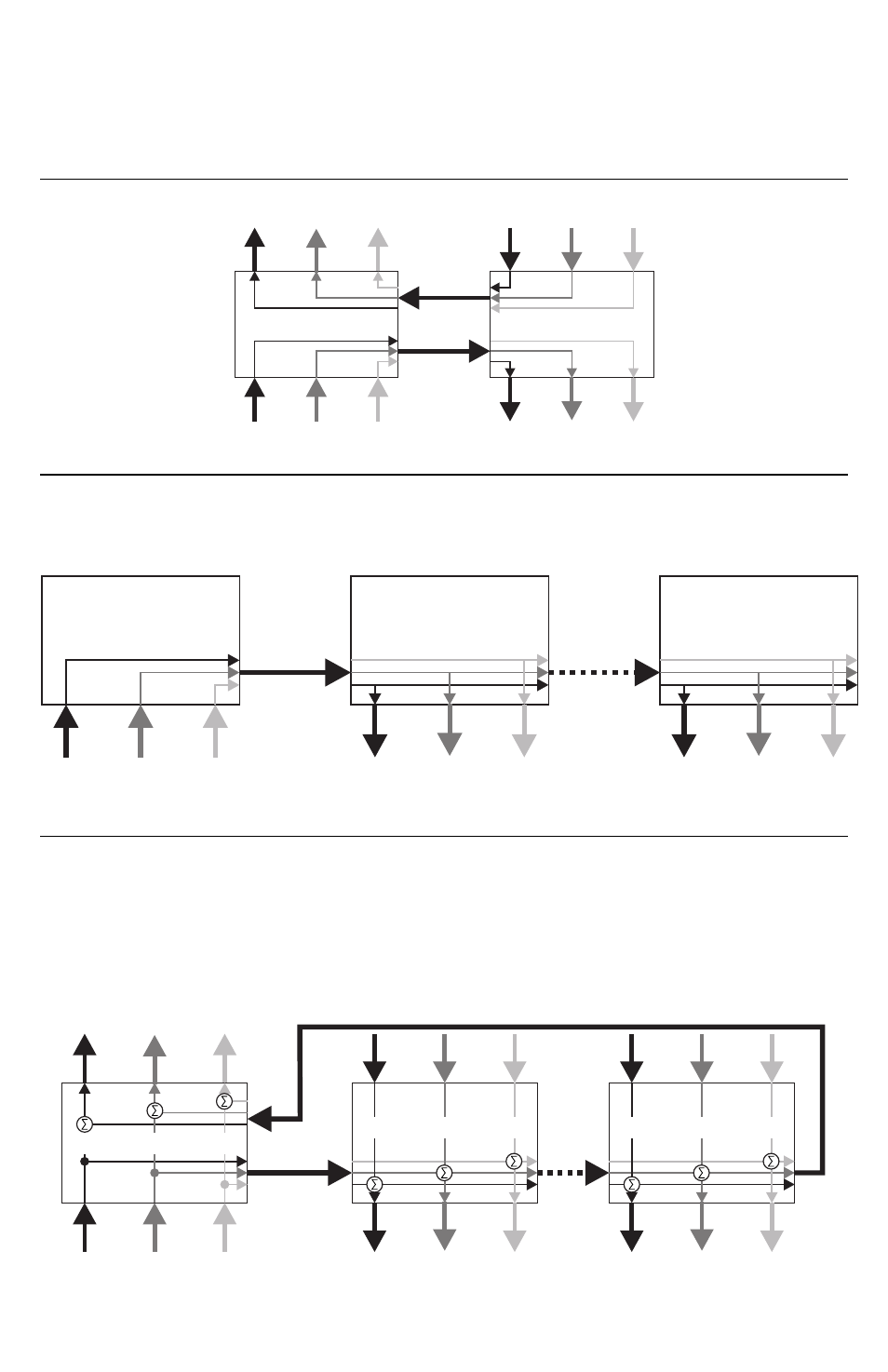
The first unit is configured as the master, which sets the clock and sample rate, the other, as the slave. Audio
inputs one unit map directly to audio outputs on the other unit. Serial data and contact closures are a direct
connection.
The first unit is configured as the master, which sets the clock and sampling rate. Audio, control and serial
inputs on the master are sent to all the slaves, which output the data on their respective ports. No
communication is sent from the slaves back to the master or to each other.
The master sends the audio from its inputs to the next unit with each successive unit in the loop adding its
own input to the aggregated sample, gated by its push to talk, if enabled. When the aggregated sample
returns back to the master, it then sends out that aggregated sample as the output for all units in the loop. All
units forward the aggregated output around the loop until it returns to the master, which discards it. Serial
data and control are also aggregated, such that any Control Activation Input on any unit causes all units to
activate their Control Relays. Likewise, if any unit’s serial input is non‐idle, all units will then output a non‐idle
condition.
Unit 1
Unit 2
Unit n
(Broadcast Master)
(Slave)
(Slave)
Audio
Audio
Audio
Serial
Fiber
Fiber
Serial
Serial
Control
Control
Control
Unit 1
Unit 2
Unit n
(Intercom Master)
(Slave)
(Slave)
Fiber
Fiber
Audio
Serial
Audio
Serial
Control
Control
Audio
Serial
Control
Unit 1
Unit 2
(Point to Point Master)
(Slave)
Audio
Audio
Serial
Fiber
Serial
Control
Control