Front indicators/connections – FiberPlex TD-7280 User Manual
Page 6
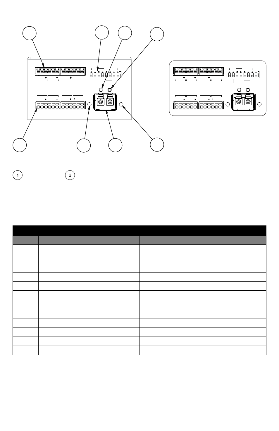
Front Indicators/Connections
Figure 1 TD‐7280 (left) and FOI‐7280 (right) Front Face
Input Pins 1‐12 &
Output Pins 13‐24 – These headers contain all of the I/O for the 7280 interface.
Connections can be made using the included Phoenix™ Spring‐cage plug (P/N 1778874). Wire ranging from 26‐
20 AWG can be inserted directly into the spring‐cage without tools (see “Using Phoenix Connectors” later in
the manual for more information). Audio connections are grouped on pins 1‐6 (inputs) and 13‐18 (outputs),
Serial Data connections are found on pins 7‐9 (RX) and 19‐21 (TX) Control activation is on 10‐12 and Relay
contact closures are on 22‐23. See “Connection Details” later in the manual for specifics related to each type
of I/O port. Below is a detailed pinout for these connections:
CONNECTOR PINOUTS
Pin
Description
Pin
Description
1
Audio in 1 minus
13
Audio out 1 minus
2
Audio in 1 plus (unbal)
14
Audio out 1 plus (unbal)
3
Audio in ground
15
Audio ground
4
Audio in 2 minus
16
Audio out 2 minus
5
Audio in 2 plus (unbal)
17
Audio out 2 plus (unbal)
6
Audio ground
18
Audio ground
7
Serial in minus
19
Serial out minus
8
Serial in plus
20
Serial out plus
9
Serial Ground
21
Serial Ground
10
Relay ground
22
Relay out common
11
Relay in, ground to activate
23
Relay out Normally Open (NO) contact
12
Relay in, minus 6‐48V to activate
24
Relay out Normally Closed (NC) contact
PWR
STAT
TX
RX
+
+
+
S -V
+
+
NO NC
+
-
-
-
-
-
C
-
Audio
Serial Relay
1
1
2
2
In
In
RX
Ou t
Ou t
TX
13
1
24
12
1
8
Unbal
PTT
Network
Serial Mode
Term
Idle
1
2
5
3
4
6
7
8
P
S
TX
RX
+
+
+
S -V
+
+
NO NC
+
-
-
-
-
-
C
-
Audio
Serial Relay
1
1
2
2
In
In
RX
Ou t
Ou t
TX
1
8
Unbal
PTT
Network
Serial Mode
Term
Idle