3 target evaporator exit temperature output form, 2 target evaporator exit temperature input form – Fieldpiece HG2 - HVAC Guide System Analyzer User Manual
Page 8
14
WWW.FIELDPIECE.COM WWW.FIELDPIECE.COM WWW.FIELDPIECE.COM WWW.FIELDPIECE.COM WWW.FIELDPIECE.COM WWW.FIIELDPIECE.COM WWW.FIELDPIECE.COM WWW.FIELDPIECE.COM WWW.FIELDPIECE.COM WWW.FIELDPIECE.COM WWW.FIELDPIECE.CO
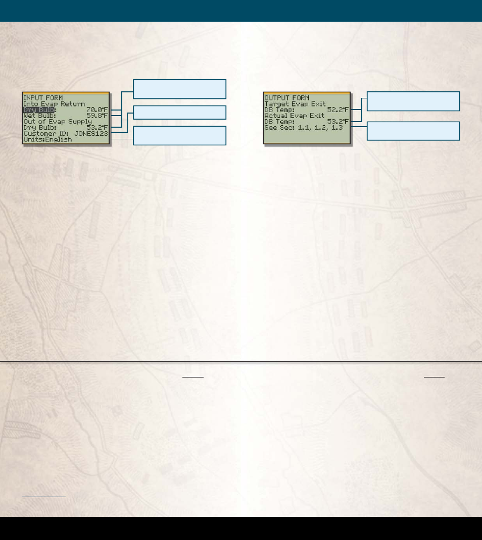
1.3 Target Evaporator Exit Temperature
OUTPUT FORM
Figure 5. OUTPUT FORM for Target Evaporator Exit Temperature.
Press OUTPUT for the Target Evaporator Exit Tem-
perature OUTPUT FORM.
Target Evap Exit DB Temp
(Target Evaporator
Exit Dry Bulb Temperature): Th
is is the target exit
temperature based on the measured indoor condi-
tions.
Actual Evap Exit DB Temp
(Actual Evaporator
Exit Dry Bulb Temperature): Th
is is the measured
temperature of the air in the supply.
Th
e
Actual Evap Exit DB Temp
should be
within ±3°F of the
Target Evap Exit DB Temp
. If
the temperature is outside of this range, the technician
should make modifi cations to correct the problem.
1.2 Target Evaporator Exit Temperature
INPUT FORM
Figure 4. INPUT FORM for Target Evaporator Exit Temperature.
Into Evap Return Dry Bulb
and
Wet Bulb:
Take
measurements as close to the inlet of the air handler
as possible. If the fi lter is just before the air handler,
the easiest way is to clip an ATWB1 and ATA1 to the
fi lter on the side facing the evaporator and take the
measurements. If the fi lter is not before the evapo-
rator, make small holes in the return plenum just big
enough for the probes. Seal any holes before leaving
the jobsite.
Out of Evap Supply DB
(dry bulb temp leaving
the evaporator): Measure in the center of the supply
plenum. Punch a small hole in the supply plenum
and insert a calibrated dry bulb thermocouple such
as the ATA1 or ATB1. Make sure the thermocouple
is in the center of the plenum cross-section. Seal the
hole when fi nished.
Can be measured automatically with
Fieldpiece accessory heads.
Units can be changed to either English
or Metric.
Customer ID is useful for record keeping.
Sections of manual with more
information about this test.
If Target and Actual are more than 3°F
apart a modification is needed.
An
Actual Evap Exit DB Temp
above the
Target Evap Exit DB Temp
usually indicates low
capacity. Occasionally airfl ow is higher than expected.
Look for causes of low capacity such as refrigerant mis-
charge or dirty condenser coil. If the airfl ow is high,
correct by lowering the fan speed.
Because everything within the system is inter-de-
pendent, one adjustment can aff ect other parts of the
system. For example, increasing airfl ow increases the
superheat, which may require adding refrigerant. Aft er
modifi cations, allow 15 minutes to stabilize and then
retest.
An
Actual Evap Exit DB Temp
below the
Target Evap Exit DB Temp
indicates low airfl ow.
Increasing airfl ow can be accomplished by elimi-
nating restrictions in the duct system, increasing blower
speed, cleaning fi lters or opening registers. Aft er cor-
rective measures are taken, repeat measurement proce-
dures as oft en as necessary to establish adequate airfl ow
range. Allow system to stabilize for 15 minutes before
repeating measurement procedure.
1
1 2005 Residential ACM Manual, Page RD-5, (#5-7)
A
l
T
A
l
T