Installation requirements (cont.) – Fire Magic Regal I 34 series Drop In User Manual
Page 10
REV 3 - 1407091450
L-C2-005
10
This is a drop-in type unit designed to fi t into countertop
enclosures. The top panel of the unit is removable for
gas hookup, servicing and burner adjustment.
The top panel MUST remain removable for servicing
(see PARTS LIST).
Note: This unit should be installed so that it can be
removed at a later date if factory service is
required. Any protrusion into the barbecue
enclosure may obstruct the frame and prevent
the unit from dropping into place (see GAS
SUPPLY PLUMBING REQUIREMENTS).
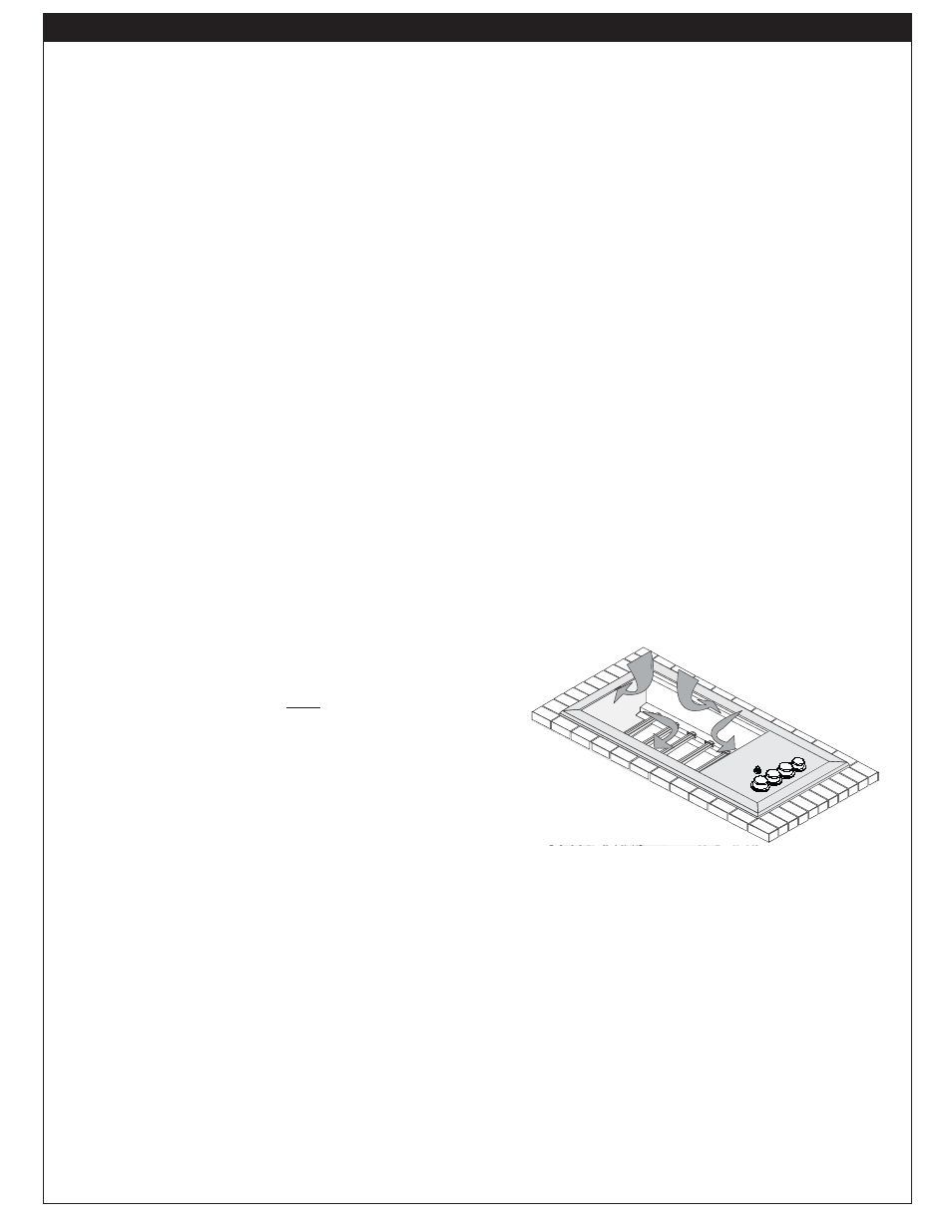
ENSURING PROPER COMBUSTION AIR AND
COOLING AIRFLOW
Proper airfl ow (Fig. 10-1) MUST be maintained for the
grill to perform as it was designed. If airfl ow is blocked,
overheating and poor combustion will result. Do not block
the air inlet around the inside edges of the top panel or
more than 75% of the cooking grid surface with pans
or griddles.
EXHAUST REMOVAL
If installed or used under a patio roof, the cooking grid
area must be fully covered by an exhaust hood with a
vent. An exhaust fan with a rating of 1,000 CFM (cubic
feet per minute) or more may be necessary to effectively
remove smoke and other cooking by-products from
the area under the hood. Fire Magic Vent Hoods are
available to meet this requirement. This grill must
not be used under unprotected overhead combustible
construction. THIS UNIT MUST NOT BE LOCATED IN
A FULLY ENCLOSED AREA OF ANY KIND.
GAS-SUPPLY PLUMBING REQUIREMENTS
For natural gas or a household propane system, rigid
1
/
2
" or
3
/
4
" black steel pipe or local code-approved pipe
is required to conduct the gas supply to the unit. Contact
your local gas supplier. Connect this pipe to a required
C.S.A.-approved stainless-steel fl ex connector. DO NOT
use a rubber hose within the grill enclosure. Apply
only joint compounds that are resistant to all gasses to
all male pipe fi ttings except fl are fi ttings. Make sure to
tighten every joint securely.
The gas supply pipe should enter from the fl oor, or
from the back or side wall in the right rear corner of
the barbecue enclosure, behind the valve control zone.
This pipe should terminate with a
1
/
2
" male pipe thread,
situated within 12" of the countertop and no more
than 5" from the back and side walls. See the MODEL
SPECIFICATIONS section for details.
Note: If
1
/
2
" pipe is used with natural gas, it should
be no longer than 20'.
Important:
An external valve (with a removable
key) in the gas line is necessary for
safety when the grill is not in use. It also
provides for convenient maintenance.
CAUTION: Wind blowing into or across the rear
oven lid vent (if applicable) can cause
poor performance and/or dangerous
overheating. Orient the grill so that the
prevailing wind blows toward the front of
the grill.
GAS SUPPLY AND MANIFOLD PRESSURES:
For natural gas - normal 7" (17.78 cm) water column
(w.c.), minimum 5" (12.7 cm), maximum 10
1
/
2
" (26.7
cm). For propane gas - normal 11" w.c., minimum 10"
(25.4 cm), maximum 13" (33 cm).
INSTALLATION REQUIREMENTS (CONT.)
Fig. 10-1
- Ventilation Diagram
Vents at
Cylinder Le