Checking/converting the burner orifices (cont.) – Fire Magic Regal I 34 series Drop In User Manual
Page 17
17
AIR SHUTTER
SCREW
CHECKING/CONVERTING THE BURNER ORIFICES (Cont.)
6. Pull the backburner assembly to the left, clear of the
orifi ce, and then rotate the top forward and downward
and lay it face down across the main burner dividers.
CAUTION: Be careful not to damage the wires
connected to the backburner assembly.
7. Use the socket driver to remove the exposed orifi ce
and replace it with the correct orifi ce for the gas to be
burned (see the MODEL SPECIFICATIONS TABLE
for correct orifi ce sizes, based on burner type and
gas type).
8. Replace the backburner assembly and re-insert the
anchoring screw. Center the backburner assembly
so that the backburner face place will fi t over it.
Tighten the anchoring screw using a Phillips-head
screwdriver.
9. While the backburner faceplate is still off, adjust the
backburner air shutter opening size by loosening
the air shutter adjustment screw with a fl at-head
screwdriver and sliding the air shutter to the position
indicated in the MODEL SPECIFICATIONS TABLE;
then re-tighten the adjustment screw. (see section
on AIR SHUTTER ADJUSTMENT).
10. Replace the backburner face plate by fi rst inserting
the upper tabs into the slots in the back wall of the
barbecue and then rotating the bottom downward
and inward.
11. Replace the two backburner faceplate screws using
a Phillips-head screwdriver.
Tip: Re-attaching the backburner faceplate may be
easier if the left screw is replaced before the right
screw.
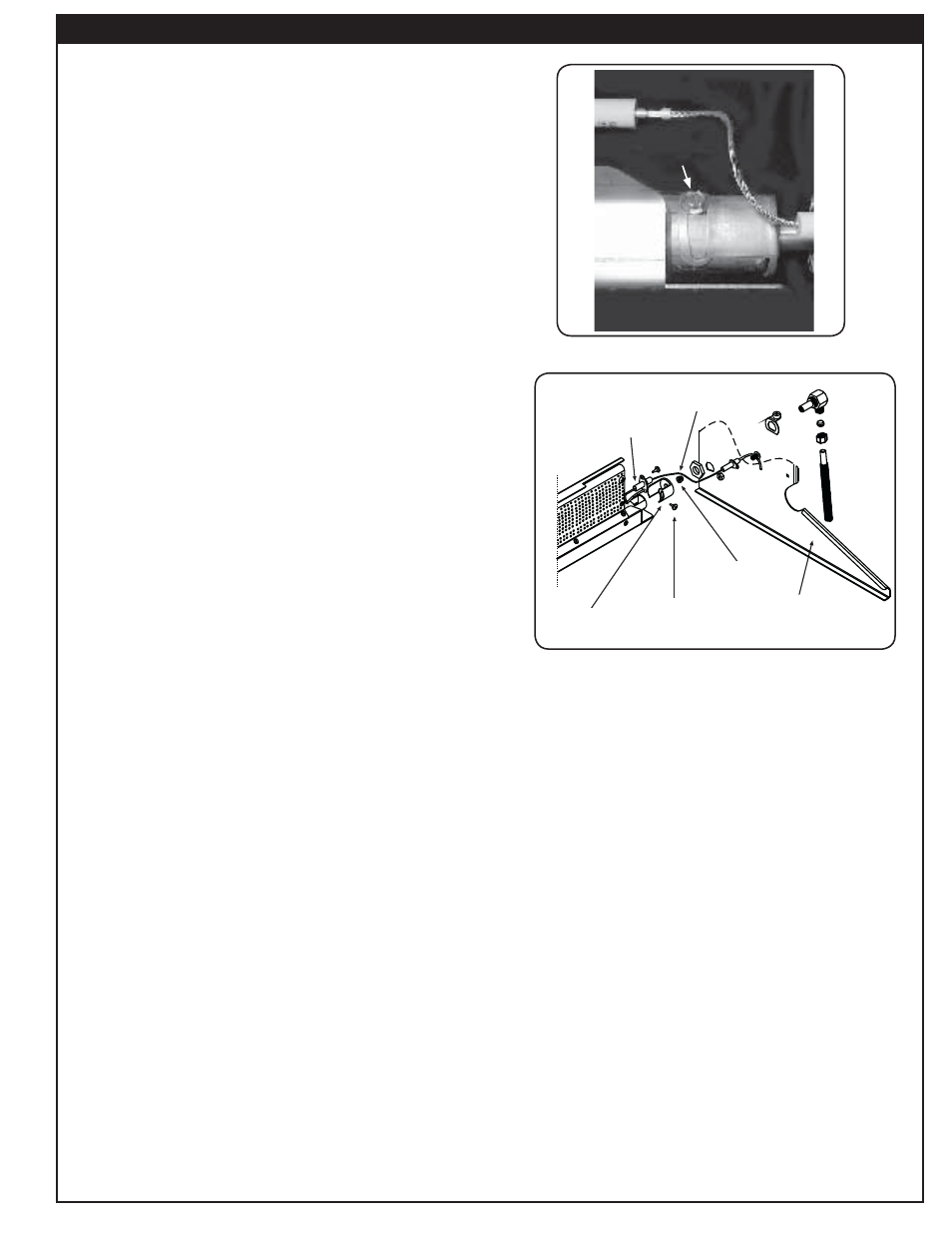
THE BACKBURNER COVER
The backburner cover is installed by placing the curved
part of the cover over the top of the perforated portion
of the backburner (see
Fig. 17-2
). The cover should be
kept in place on the backburner when it is not in use. This
will keep your backburner free from grease splatter and
debris that may hinder its performance.
Important: You must remove the backburner cover
before lighting the backburner.
Fig. 17-2
Ignitor wire
Orifice
Air
shutter
Electrode
Oven
(right side)
Air shutter
screw
IGNITOR WIRE
ELECTRODE
AIR
SHUTTER
AIR SHUTTER
SCREW
ORIFICE
OVEN
(RIGHT SIDE)
Fig. 17-1