Fire Magic 4199-68 electrode User Manual
Fire Magic Hardware
1
Model No. 4199-68
BACKBURNER ELECTRODE
REPLACEMENT KIT
(PRE-YEAR 2000 UNITS)
REV A 030305
No. L-C2-07105
ROBERT H. PETERSON CO. • 14724 East Proctor Avenue • City of Industry, CA 91746
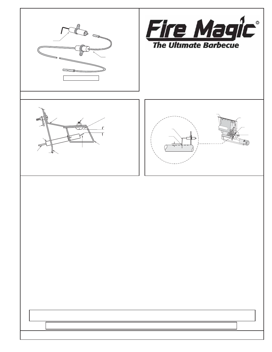
Figure 1
BACKBURNER ELECTRODE ASSEMBLY
Electrode
Electrode Wire
(Part # 4199-68)
ELECTRODE
WIRE
MOUNTING
BRACKET
BBQ LINER
COLLECTOR
BOX
ELECTRODE
GROUND
WIRE
ELECTRODE
CERAMIC
5/32
* 5/32 on Backburner BBQs
ADJUSTING
SCREW
GROUND POINT
BACKBURNER
ELECTRODE
ELECTRODE
OVER GAS PORT
IN BURNER PIPE
5/32"
1
2
3
BURNER PIPE
BACKBURNER
COVER
ELECTRODE
MOUNTING SCREW
CAUTIO
N
REMOVE
THIS
COVER
BEFORE
LIGHTING YOUR BACK BURNER.
TOP HEAT
DEFLECTOR
ELECTRODE
Figure 2
Figure 3
INSTALLATION OF THE BACKBURNER ELECTRODE
1. Remove the backburner cover and unplug the
backburner electrode wire (Figure 1 and 3).
2. Use a Phillips screwdriver to remove the mounting
screw at the left end of the backburner (see Owner’s
Manual for more details on removing backburner).
Be cautious not to lose the spacer bushing that holds
the burner away from the mounting bracket.
3. Carefully move the left end of the backburner
assembly forward while pulling it gently away from
the orifice holder which supports the right end of the
burner. Remove the burner assembly from the
barbecue oven.
4. Use a 1/4” socket screwdriver or a small wrench to
remove the electrode mounting screw (Figure 3).
Check the new electrode to see if the plug on the
electrode wire matches the plug on the new electrode
(Figure 1). If the plug fits, inspect the electrode wire
insulation for fraying or other damage. If the plug
doesn’t fit, the wire must be replaced at this time.
5. To replace the electrode wire, remove the screw on
the side of the oven and replace the old wire with
the new one. Follow instructions in the installation
and operating manual for removal of the face or top
panel. The wire match holder provided with the
barbecue may be helpful to pull the electrode wire
forward inside the barbecue frame.
6. If the spark generator (on the face or top panel of
the barbecue) has plugs for three wires, the ground
wire must be plugged into the center plug. The
barbecue and backburner electrode wires can be
plugged into either outside plug. If the generator has
two plugs, there will be no ground and it makes no
difference which plug the electrodes plug into.
7. Before reassembling the backburner and face, check
the electrode gap for barbecue and backburner
(Figure 2 and 3). Also, before fully reassembling, plug
in all wires and check for spark at both electrodes. A
small mirror will be helpful for checking the barbecue
electrode spark.
8. Follow instructions in the barbecue manual for air
shutter adjustment, then reassemble.
This manual may not be copied, photocopied, reproduced, translated, or published in any electronic or
machine-readable form in whole or in part without prior written approval of Robert H. Peterson Co.
We reserve the right to amend product specifications without prior notice.