1 grouting of a pump with levelling plate, Adjusting the levelling plate – Flowserve PVML User Manual
Page 12
PVML USER INSTRUCTIONS ENGLISH 00079591 – 01/05
4.4.1
Grouting of a pump with levelling plate
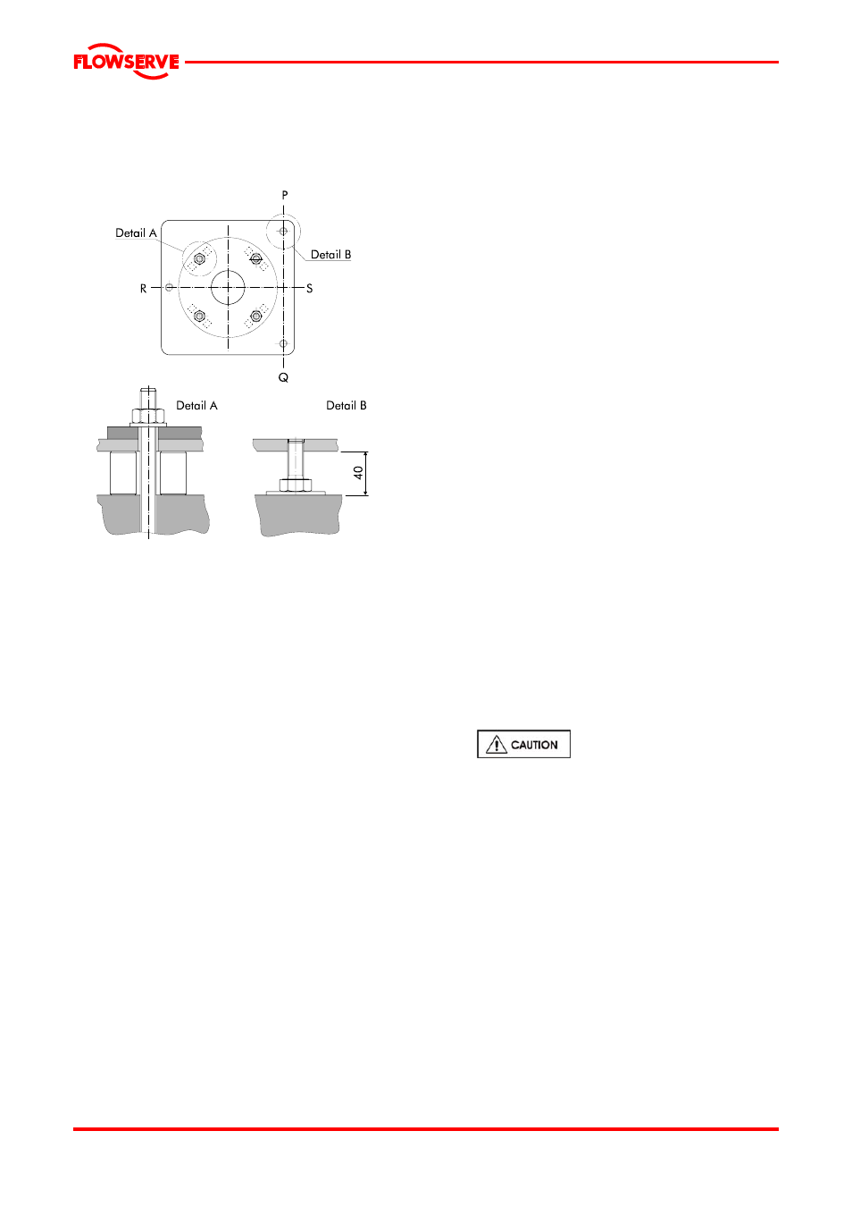
See below figure for the following procedures.
lay steel filler blocks on the base on either side of
the foundation bolts;
place the foundation bolts with nuts in the levelling
plate;
place the levelling plate on the filler blocks;
lay thin filler plates under the adjusting bolts;
remove the nuts from the foundation bolts;
place the pump unit on the levelling plate in
accordance with the lifting instructions described
in § 3.1. The bolt holes in the base of the pump
should correspond with the bolt holes in the
levelling plate;
replace the nuts on the foundation bolts;
adjust the pump unit so that it is roughly level and
at the required height by turning the adjusting
bolts in the levelling plate. Position the levelling
plate so that the suction and discharge flange can
be mounted on the pipe flanges without stress.
There should be a parallelism of 0.1 mm between
the flanges to be connected;
fill the space between the filler blocks and the
levelling plate with filler plates;
check that the bolts fit easily into the bolt holes of
the flanges;
fix the foundation bolts by filling the recesses with
non-shrinkable mortar;
let the mortar wet in accordance with the
specifications.
4.4.1.1 Adjusting the levelling plate
To make sure that the unit is level, use a calibrated
machine level with an accuracy of 0.02 mm/m
1
.
Measure along the shaft of the electric motor in
both directions or, if this is not possible, along the
seal plate. If the mechanical seal is fitted with a
guard, this should be removed.
level the levelling plate in the direction P-Q with
an accuracy of 0.15 µm/m (0.002 in./ft) using
the adjusting bolts (see Figure 5). Fill the space
between the filler blocks and the levelling plate
with thin filler plates;
level the levelling plate in the directions R-S
with an accuracy of 0.15 µm/m (0.002 in./ft)
using the adjusting bolt. Fill the space between
the filler blocks and the levelling plate with thin
filler plates;
tighten the foundation nuts provisionally by
applying a moment equal to ¼ the maximum
permissible moment (M
max
) of the foundation
bolt;
check the position and level along the
centreline of the suction and discharge
nozzles. Adjust, if necessary, by following the
procedures given above;
fill in the outer edges of the levelling plate,
including filler plates, completely using non-
shrinkable mortar (e.g. Pagel V1 or equivalent)
and let this cure in accordance with the
specifications;
remove the foundation nuts and the pump unit
from the levelling plate;
grout the levelling plate, via the
fill opening, completely using non-shrinkable
concrete and let this cure in accordance with
the specifications;
replace the pump unit on the levelling plate and
locate the foundation nuts with washers;
tighten the foundation nuts permanently by
applying a moment equal to ¼ the maximum
permissible moment (M
max
) of the foundation
bolt;
if the guard of the mechanical seal was
removed for levelling, replace it in the correct
position;
if necessary, draw up a report on the whole
adjustment procedure.
4.4.1
Grouting of a pump with base plate or
extended levelling plate
Page 12 of 29