Installing the mechanical seal, Fitting the electric motor, Fitting the motor stool – Flowserve PVML User Manual
Page 23: Fitting the impeller
PVML USER INSTRUCTIONS ENGLISH 00079591 – 01/05
6.9.4
Installing the mechanical seal
This procedure describes assembly of the mechanical
seal to the casing cover.
Clean the supporting surfaces of the mechanical
seal and the casing cover.
Place a new packing ring [see seal dwg.] in the
casing cover or O-ring on the seal plate,
depended from the seal type.
Place the mechanical seal in the casing cover in
accordance with the instructions for use provided
by the relevant supplier.
Tighten the nuts [6581.2] for fixing the mechanical
seal to the casing cover by applying the
prescribed torque, see section 6.5.
6.9.5
Fitting the electric motor
This procedure describes assembly of the electrical
motor to the motor stool.
If the pump is provided with an Inpro seal, it must
be mounted first; for instructions see suppliers
documentation.
Attach the lifting devices to the appropriate lifting
points. Observe the lifting instructions described in
section 2.3.
The lifting lugs fixed to the motor
are sufficient to lift the motor, but are not suitable
to lift the total unit.
Place the bottom of the motor stool on a support
due to the protruding shaft of the electric motor.
Clean the mounting surfaces of the electric motor
and the motor stool.
Carefully lower the flange of the electric motor
vertically onto the motor stool. Make sure that the
centring rims are not damaged.
Assemble the hexagon head screws [6577.3].
Fix the thrower [2540] on the shaft of the electric
motor. Keep a distance of about 5 mm between
the thrower and the electric motor.
6.9.6
Fitting the motor stool
This procedure describes assembly of the motor stool
to the casing cover.
Clean the mounting surfaces of the motor stool
and the casing cover.
Carefully place the shaft of the electric motor in
the shaft sleeve so that the motor stool is resting.
Tighten the bolts [6577.2].
6.9.7
Fitting the impeller
This procedure describes assembly of the impeller
to the shaft of the electric motor.
Attach the lifting devices to the appropriate
lifting points and observe the lifting instructions
described in section 2.3.
Lift up the electric motor, the motor stool and
the casing cover as a single assembly so that
the end of the shaft of the electric motor is
easily accessible.
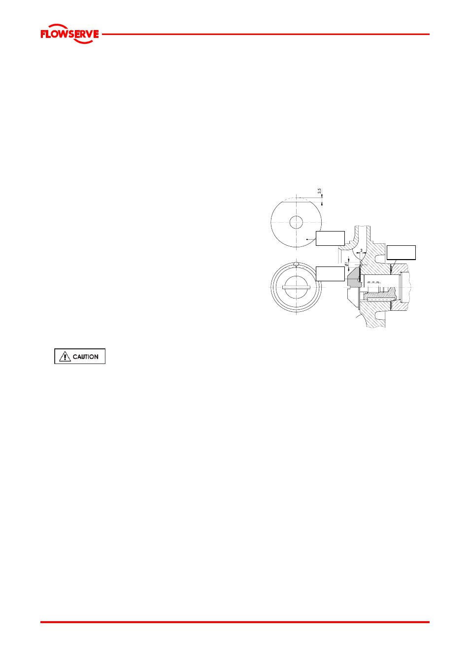
4590.4
4590.3
4590.4
Figure: Locking impeller screw
Place the key [6700] in the shaft of the electric
motor with the beveled side towards the
outside of the shaft of the electric motor in the
direction of the electric motor. See Figure.
Place a new packing ring [4590.3] against the
shaft sleeve of the mechanical seal.
Slide the impeller over the shaft of the electric
motor.
Fit a new packing ring [4590.4] according to
Figure.
Place the packing ring [4590.4] on the impeller
screw [2913] with the cut off edge at the bore
hole.
Turn the impeller screw to the left by applying
the prescribed torque, see section 6.5. Make
sure that the cut off edge of the packing ring
[4590.4] remains in.
Lock the impeller screw by knocking the edge
of the impeller screw into the bore hole in the
impeller using a hammer and a centre punch.
Release the mounting of the shaft sleeve of the
mechanical seal by sliding back the face plates and
secure these in the retracted position.
Page 23 of 29