5 initial alignment, 1 thermal expansion, 2 alignment methods – Flowserve PVML User Manual
Page 13: 6 piping, 5 initial alignment 4.6 piping
PVML USER INSTRUCTIONS ENGLISH 00079591 – 01/05
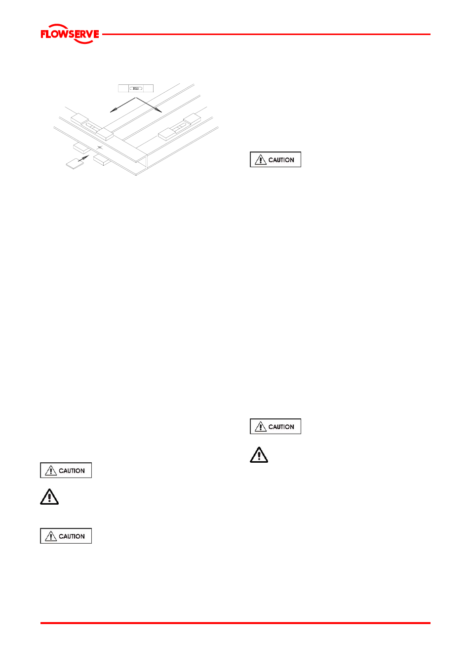
a) Install the base plate or extended levelling plate
onto packing pieces evenly spaced and adjacent
to foundation bolts.
b) Level with shims between base plate and packing
pieces [accuracy in both directions 0.15 µm/m
(0.002 in./ft)]
Where applicable, grout in the foundation bolts.
After adding pipework connections the baseplate
should then be grouted in accordance with good
engineering practice. Fabricated steel baseplates can
be filled with grout. If in any doubt, please contact your
nearest service centre for advice.
Grouting provides solid contact between the pump unit
and foundation, prevents lateral movement of running
equipment and dampens resonant vibrations.
Foundation bolts should only be fully tightened when
the grout has cured.
4.5 Initial alignment
4.5.1 Thermal expansion
The PVML pump and motor are designed such that
they will cope with the thermal expansion for pump
application and cope with the pumping temperature as
specified on the pump data sheet. There is no need to
check the alignment at normal service conditions.
4.5.2 Alignment methods
The alignment of the pump with the
piping MUST be checked.
Complete piping as below.
4.6 Piping
Protective covers are fitted to the pipe
connections to prevent foreign bodies entering during
transportation and installation. Ensure that these
covers are removed from the pump before connecting
any pipes.
4.6.1 Suction and discharge pipework
In order to minimize friction losses and hydraulic
noise in the pipework it is good practice to choose
pipework that is one or two sizes larger than the
pump suction and discharge. Typically main
pipework velocities should not exceed 2 m/s (6
ft/sec) suction and 3 m/s (9 ft/sec) on the
discharge.
Take into account the available NPSH which must
be higher than the required NPSH of the pump.
Never use the pump as a support
for piping.
Maximum forces and moments allowed on the
pump flanges vary with the pump size and type. To
minimize these forces and moments that may, if
excessive, cause misalignment, hot bearings,
vibration and the possible failure of the pump
casing, the following points should be strictly
followed:
• Prevent excessive external pipe load
• Never draw piping into place by applying force
to pump flange connections
• Do not mount expansion joints so that their
force, due to internal pressure, acts on the
pump flange
The table on the general arrangement drawing
summarizes the maximum forces and moments
allowed on PVML pump casings. The allowable
forces and moments are also listed in the
addendum (Tab 1) . Refer to Flowserve for other
configurations.
Mount the flanges of the pipes and pump so that
they are parallel with a tolerance of 0.1 mm. Make
sure that the centrelines of the flanges are in line
with each other.
Ensure piping and fittings are
flushed before use.
Ensure piping for hazardous liquids is
arranged to allow pump flushing before removal of
the pump.
4.6.2 Suction piping
a) The inlet pipe should be one or two sizes larger
than the pump inlet bore and pipe bends
should be as large a radius as possible.
b) Pipework reducers should have a maximum
total angle of divergence of 15 degrees.
c) Keep the total length of the suction pipe as
short as possible.
d) A bend in the suction pipe should be located at
a distance of at least 5 times the pipe bore from
the suction flange
Page 13 of 29