4 removing the electric motor, 5 removing the mechanical seal, 5 removing the case wearing rings – Flowserve PVML User Manual
Page 21: 6 removing the impeller wearing rings, 7 removing the neck bush, 8 examination of parts
PVML USER INSTRUCTIONS ENGLISH 00079591 – 01/05
6.7.4
Removing the electric motor
This procedure describes removal of the electric motor
from the motor stool. .
Place the bottom of the motor stool on a support
due to the projecting shaft of the electric motor.
If the pump is provided with an Inpro Seal, first
release the thrower [2540]. For disassembly
instructions see suppliers documentation.
Remove the hexagon head bolts [6577.3].
Lift the electric motor up vertically. Make sure that
the centring rims are not damaged.
Remove the thrower [2540] from the shaft of the
electric motor.
6.7.5 Removing the mechanical seal
This procedure describes removal of the mechanical
seal from the casing cover.
Remove the nuts [6581.2] from the mechanical
seal on top of the cover.
Remove the mechanical seal.
Do not dismantle the mechanical seal any further.
For further information on the mechanical seal, please
refer to the instructions for use provided by the
relevant supplier.
6.7.5 Removing the case wearing rings
This is the procedure to be followed when removing
the case wearing ring from the diffuser and, if
applicable, the case wearing ring in the casing cover.
This depends on the structural design.
The case wearing ring has been pressed or shrunk
into the centring rim during assembly which means
that it will be necessary to drill or cut into the case
wearing ring in order to weaken the upright edge.
Remove the set screws [6570.1]. These set
screws lock the case wearing ring against the
diffuser [1410].
Measure width & height of the case wearing ring.
Take a drill with a slightly smaller diameter than
the width of the case wearing ring.
Drill two holes along
the centre line of the
upright edge of the
case wearing ring,
see Figure. Drill both
holes not deeper than
the measured height
of the case wearing
ring.
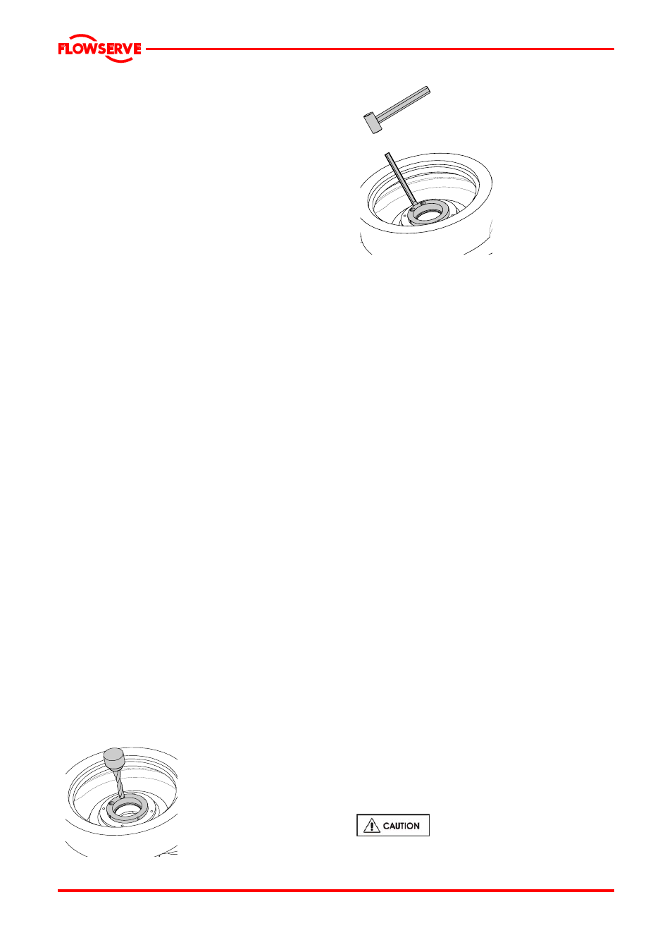
Chip off the
remaining edges
of the drilled holes
using a hammer
and chisel, see
Figure. Make sure
that the centring
rim is not
damaged.
Remove the
halves of the case
wearing ring and
the metal chips
from the pump
casing or casing
cover.
6.7.6 Removing the impeller wearing rings
The impeller wearing rings [2300.1 & 2] have been
shrunk or pressed onto the impeller during
assembly. Therefore a suitable extraction tool must
be used for disassembly.
Remove set screws [6570.2]. These set screws
lock the impeller wearing ring against the
impeller.
Remove the impeller wearing ring from the
impeller using the extraction tool.
Drill 3 holes at 120
° intervals in the partition
between impeller wearing ring and impeller.
Drill the holes to a depth such that the set
screws [6570.2] do not protrude above the
surface of the impeller wearing ring and
impeller.
6.7.7 Removing the neck bush
This procedure describes removal of the neck
(throttle) bush from the casing cover.
Remove set screws [6570.3] from the bottom of
the casing cover. These set screws lock the
neck bush [4132] against the casing cover.
Remove the neck bush from the casing cover.
If this cannot be done by hand, remove it from
the casing cover by tapping with a suitable
copper rod and a hammer.
6.8 Examination of parts
Used parts must be inspected
before assembly to ensure the pump will
subsequently run properly.
Figure : Drilling of the case wearing
Figure : Removing the case
wearing ring
Page 21 of 29