Flowserve MN User Manual
Page 16
MN USER INSTRUCTIONS ENGLISH 71569189 11/04
Page 16 of 49
®
The foundation should be of sufficient strength to
absorb vibration (i.e., at least five times the weight of
the pump unit) and to form a permanent, rigid support
for the baseplate. This is important in maintaining
the alignment of a close-coupled unit. A concrete
foundation on a solid base should be satisfactory.
4.3.1 Pump and structural natural frequency
Pump manufacturers can calculate or determine the
natural frequency of the pump assembly, including
the driver. However, in a field installation, the
vibrating structure comprises, in addition to the pump
assembly, the foundation, the mounting, the piping,
and supports. The natural frequency of the vibrating
structure is determined by the stiffness of the total
structure and by its equivalent mass. The natural
frequency of the structure may therefore differ
significantly from the natural frequency of the pump.
In the absence of any specific information, the pump
manufacturer will assume that the piping is installed
rigidly and anchored close to the pump connections.
It will also be assumed that the hold down bolts are
securely embedded in a concrete foundation of
infinite mass and rigidity.
The system designer must give proper consideration
and must ensure that the natural frequency of the
vibrating structure, as defined above, does not fall
within the pump operating speed range. That person
also must be aware of the much lower stiffness of
fabricated system structures, relative to concrete,
and the problems associated with calculating
stiffness of unconventional and composite structures.
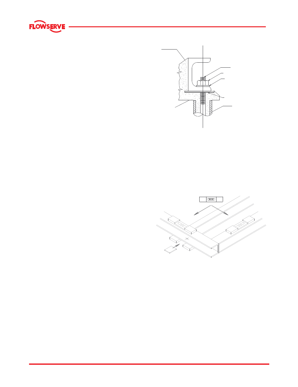
4.3.2 Typical foundation bolt arrangement
Foundation bolts of the specified size should be
embedded in concrete and located according to the
Elevation drawing. Each bolt should be surrounded
by a pipe sleeve at least two times the diameter of
the bolt. The sleeve should be held rigidly yet allow
the bolts to be moved to conform to the holes in the
baseplate as shown in the detail under this section.
FOUNDATION BOLTS
(MOTOR END)
NUT
LOCK WASHER
PUMP BASE
SHIM
PIPE SLEEVE
GROUT
SLOPE THE GROUT
TO DRAIN POCKET
FOUNDATION
4.3.3 Baseplate installation
a) The baseplate should be mounted onto a firm
foundation, either an appropriate thickness of
quality concrete or sturdy steel framework. (It
should NOT be distorted or pulled down onto the
surface of the foundation, but should be
supported to maintain the original alignment).
b) Install the baseplate onto packing pieces evenly
spaced and adjacent to foundation bolts as
shown in the detail below.
c) Level with shims between baseplate and sturdy
baseplate support pieces.
d) The pump and driver have been aligned before
shipment however the alignment of pump and
motor half coupling must be checked. If this is
incorrect, it indicates that the baseplate has
become twisted and should be corrected by re-
shimming.
4.3.4 Baseplate leveling.
a) Prior to grouting an initial alignment check shall
be performed to verify that coupling spacing and
final alignment can achieved without modifying
the hold down bolts.