Flowserve MN User Manual
Page 35
MN USER INSTRUCTIONS ENGLISH 71569189 11/04
Page 35 of 49
®
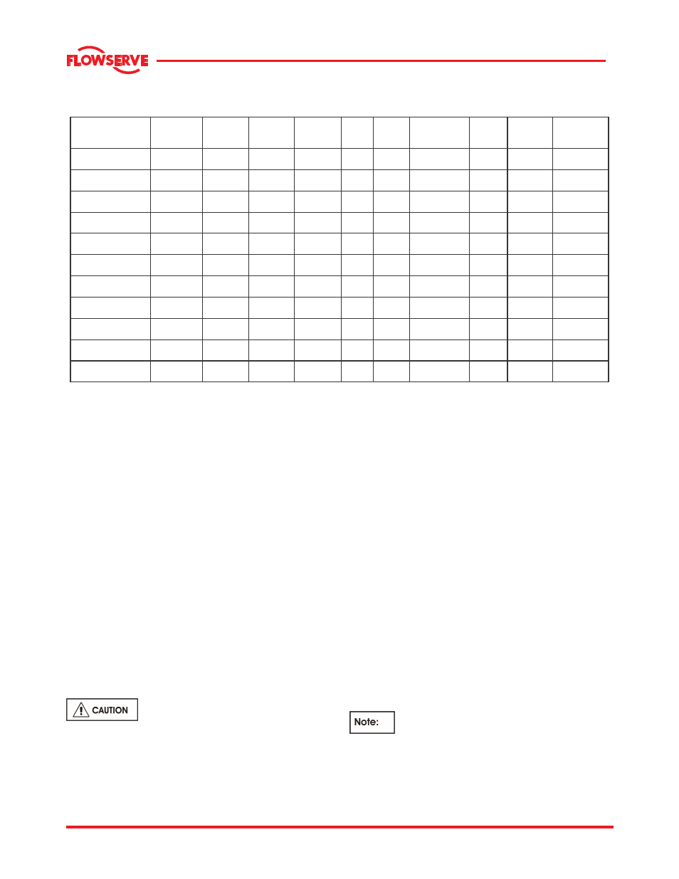
6.1.8.1 Stuffing Box Data
All dimensions in mm (In.)
Bearing
Frame
O.D.
Sleeve
(1)
I.D.
Box
(2)
Depth
of Box
Packing
Size
No.
Rings
Seal
Cage
Width
Gland
Stud Size
Gland
studs
quantity
Bolt Circle
Diameter
Distance to
First
Obstruction
4T
54.0
(2.13)
73.0
(2.87)
71.9
(2.83)
9.7
(0.38)
5
19.1
(0.75)
1/2-13NC
2
130.1
(5.12)
69.9
(2.75)
5T
70.0
(2.75)
95.3
(3.75)
95.3
(3.75)
12.7
(0.50)
5
25.4
(1.00)
5/8-11NC
2
154.9
(6.10)
85.9
(3.38)
6A
89.0
(3.50)
114.3
(4.50)
95.3
(3.75)
12.7
(0.50)
5
25.4
(1.00)
5/8-11NC
2
175.0
(6.89)
84.3
(3.32)
7L
114.0
(4.50)
139.7
(5.50)
95.3
(3.75)
12.7
(0.50)
5
25.4
(1.00)
3/4-10NC
2
190.5
(7.50)
88.9
(3.50)
7H (except
16 MN-19)
114.0
(4.50)
139.7
(5.50)
95.3
(3.75)
12.7
(0.50)
5
25.4
(1.00)
3/4-10NC
2
190.5
(7.50)
88.9
(3.50)
7H (16 MN-19)
127.0
(5.00)
158.7
(6.25)
117.3
(4.62)
15.8
(0.62)
5
31.8
(1.25)
3/4-10NC
2
215.9
(8.15)
90.4
(3.56)
8L
127.0
(5.00)
158.7
(6.25)
117.3
(4.62)
15.8
(0.62)
5
31.8
(1.25)
3/4-10NC
2
215.9
(8.15)
104.7
(4.12)
8H
127.0
(5.00)
158.7
(6.25)
117.3
(4.62)
15.8
(0.62)
5
31.8
(1.25)
3/4-10NC
2
215.9
(8.15)
104.7
(4.12)
8HA
149.3
(5.88)
187.5
(7.38)
142.7
(5.62)
19.1
(0.75)
5
38.1
(1.50)
7/8-9NC
2
264.2
(10.40)
127.0
(5.00)
9H
179.5
(7.07)
217.5
(8.56)
142.8
(5.62)
19.1
(0.75)
5
38.1
(1.50)
7/8-9NC
2
298.2
(11.74)
127.0
(5.00)
9HA
209.3
(8.24)
248.0
(9.76)
142.8
(5.62)
19.1
(0.75)
5
38.1
(1.50)
7/8-9NC
2
336.0
(13.23)
131.6
(5.18)
(1)
O.D. Sleeve tolerance is +0.00 mm/-0.13 mm (+0.000 in. /-0.005 in.) for all frames except 4T and 5T that
are + 0.00 mm/-0.05 in. (+0.000 mm/-0.002 in.)
(2)
I.D. Box tolerance is +0.00 mm/-0.13 mm (+0.000 in. /-0 .005 in.) for all frames except 4T and 5T which are + 0.05 mm/-0.00 mm
(+0.002 in./-0.000 in.)
6.1.9 Maintenance of mechanical seal
The following instruction, if adhered to, will help to
ensure a long trouble free service life for the
mechanical seal.
Most seals can be installed in a standard stuffing
box, therefore in an emergency, packing with the
addition of a seal cage and packing gland may be
utilized. Compare your seal installation drawing to
the stuffing box data provided in section 6.1.8.1.
6.1.9.1 General instructions
a) Be sure to read all seal instructions before
installing the seal.
b) A mechanical seal is a precision product. To
ensure satisfactory operation, exercise extreme
care to avoid scratching or marring the lapped
seal faces.
Rotary to stationary seal faces are
lapped to within millionths of an inch in flatness. It is
therefore important to avoid grasping the rotary seal
and compressing it against the spring, which due to
uneven loading, may cause excessive seal face
distortion and leakage upon installation
.
6.1.9.2 Preparing the pump
a) After assembling the bearing frame, shaft sleeve
and stuffing box, check the concentricity between
the bore of stuffing box and shaft sleeve. The
concentricity should not exceed the Seal
Manufacture's tolerances. Also check the sleeve
diameter and stuffing box bore dimensions to see
that they agree with those shown on seal
installation drawing.
b) Check that the face of the stuffing box is square
with the shaft sleeve to within the Seal
Manufacture's tolerances. This surface must be
smooth and flat to ensure good sealing between
the mechanical seal gland and stuffing box face.
c) Mount the rotating assembly in the pump and
adjust the wearing ring gap. Remove the rotating
assembly from the pump and scribe a line on the
shaft sleeve to mark the location of the stuffing
box face in relation to the shaft sleeve. Remove
the stuffing box head.
The wearing gap must be set before the
mechanical seal is mounted since setting the gap
relocates the shaft sleeve in relation to the stuffing
box head by as much as 6.35 mm (0.25 in.). If the
wearing gap is reset, then the mechanical seal must
be remounted.