Flowserve MN User Manual
Page 19
MN USER INSTRUCTIONS ENGLISH 71569189 11/04
Page 19 of 49
®
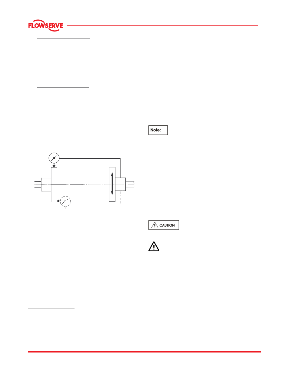
d) Check parallel alignment of the coupling halves
using a dial indicator. The dial indicator should
be mounted on the driven half-coupling with the
probe resting on the outer diameter of the driver
coupling.
Rotate the pump shaft and take readings at 90
o
intervals to check parallel alignment.
Check angular alignment of the coupling halves
with a dial indicator. The dial indicator should be
mounted on the driven half flange with the probe
resting on the driver half coupling flange. Rotate
both the driven and driver shafts together and
take readings at 90
o
intervals. The difference
between maximum and minimum dimensions is
the angular misalignment.
For couplings with narrow flanges use a dial
indicator as shown here to check both parallel and
angular misalignment.
Parallel
Angular
e) Move and shim the driver until the shafts are
accurately aligned.
f) Bolt both the pump and driver, including the
pump bearing frame support, securely to the
base and recheck the alignment per Step (d).
g) Grout the base plate to the foundation; see
section 4.4
Grouting.
h) Drill, ream, and dowel the driver feet and pump
feet to the base.
i)
Re-check alignment as in Step (d) and connect
the coupling halves and install the coupling
guard
.
4.5.4 Alignment criteria
The following maximum Total Indicator Reading (TIR)
is recommended:
Parallel Misalignment: 0.050 mm (0.002 in.)
Total Angular Misalignment: 0.025 mm (0.001 in.) per
25 mm (1.0 in.) of coupling hub radius.
When checking parallel alignment, the TIR shown is
twice the value of the actual shaft displacement.
Align in the vertical plane first, then horizontally by
moving motor. When performing final alignment,
check for soft-foot under the driver.
An indicator placed on the coupling should not
indicate more than 0.05 mm (0.002 in.) in the vertical
direction, when any driver foot fastener is loosened.
While the pump is capable of operating with the
maximum misalignment shown above, maximum
pump reliability is obtained by near perfect alignment
of 0.05 to 0.10 mm (0.002 to 0.004 in.) TIR parallel
and 0.05 mm (0.002 in.) per 100 mm (4 in.) of
coupling flange diameter as TIR angular
misalignment. This covers the full series of couplings
available.
Pumps with thick flanged non-spacer
couplings can be aligned by using a straight-edge
across the outside diameters of the coupling hubs
and measuring the gap between the machined faces
using feeler gauges, measuring wedge or calipers.
When the electric motor has sleeve bearings it is
necessary to ensure that the motor is aligned to run
on its magnetic centerline.
Refer to the motor User Instructions for
details.
A button (screwed into one of the shaft ends) is
normally fitted between the motor and pump shaft
ends to fix the axial position.
If the motor does not run in its
magnetic centre the resultant additional axial force
may overload the pump thrust bearing.
Complete piping and see sections 4.8,
Final
shaft alignment check
up to and including section 5.0,
Commissioning, startup, operation and shutdown
before connecting driver and checking actual rotation.