9 assembly – Flowserve MN User Manual
Page 42
MN USER INSTRUCTIONS ENGLISH 71569189 11/04
Page 42 of 49
®
6.9 Assembly
To assemble the pump consult the sectional
drawings, see Section 8,
Parts list and drawings
.
Ensure threads, gasket and O-ring mating faces are
clean. Apply thread sealant to sealing pipe thread
fittings.
6.9.1 Bearing Housing assembly – Oil lubricated
a) Be sure the shoulders where the bearings seat,
are free of burrs and contaminants.
b) Mount the bearing cups (outer races) [16,18] into
their respective bearing housing bores (either
chill or press in to install). Be sure the cups seat
against the bearing housing shoulders.
c) Assemble the line-bearing cone [16] on the shaft
[6] (heat or press to install).
d) Install the shaft [6], with the thoroughly oiled line-
bearing cone fitted, through the housing and
support the assembly vertically (thrust end up).
e) Heat the thrust-bearing cone to approximately 95
o
C (200
o
F) and assemble it on the shaft together
with the bearing washer, lock-washer [22A], and
locknut [22]. Hand tighten the nut.
f) Install the line bearing oil thrower (see 6.9.1.1) by
heat or press to install in the direction shown on
the sectional detail. Assemble the line bearing
inner and outer seal, line-bearing cover with
gasket, shaft sleeve, stuffing box head, impeller,
and impeller nut. Locate the impeller nut set
screw in the impeller nut fillet at assembly by
tapping a new hole in the impeller face.
A new tapped hole may be required each
time the pump is assembled. Note that there are two
impeller nut fillets located 180
o
apart and either fillet
may be used to locate the impeller nut set screw; as
shown in detail 6.9.1.2.
The line bearing oil thrower gap is not
adjustable. If the line bearing oil thrower rubs against
the line bearing cover at assembly, increase the gap
by doubling up on the line bearing cover gasket. If
for any specific application, the pump is supplied with
a line bearing thrower that is adjustable, the gap is
adjusted by following the same procedure given in
step (g) for thrust bearings.
g) Adjust the bearing endplay; See Bearing end-
play adjustment Section 6.7.4.
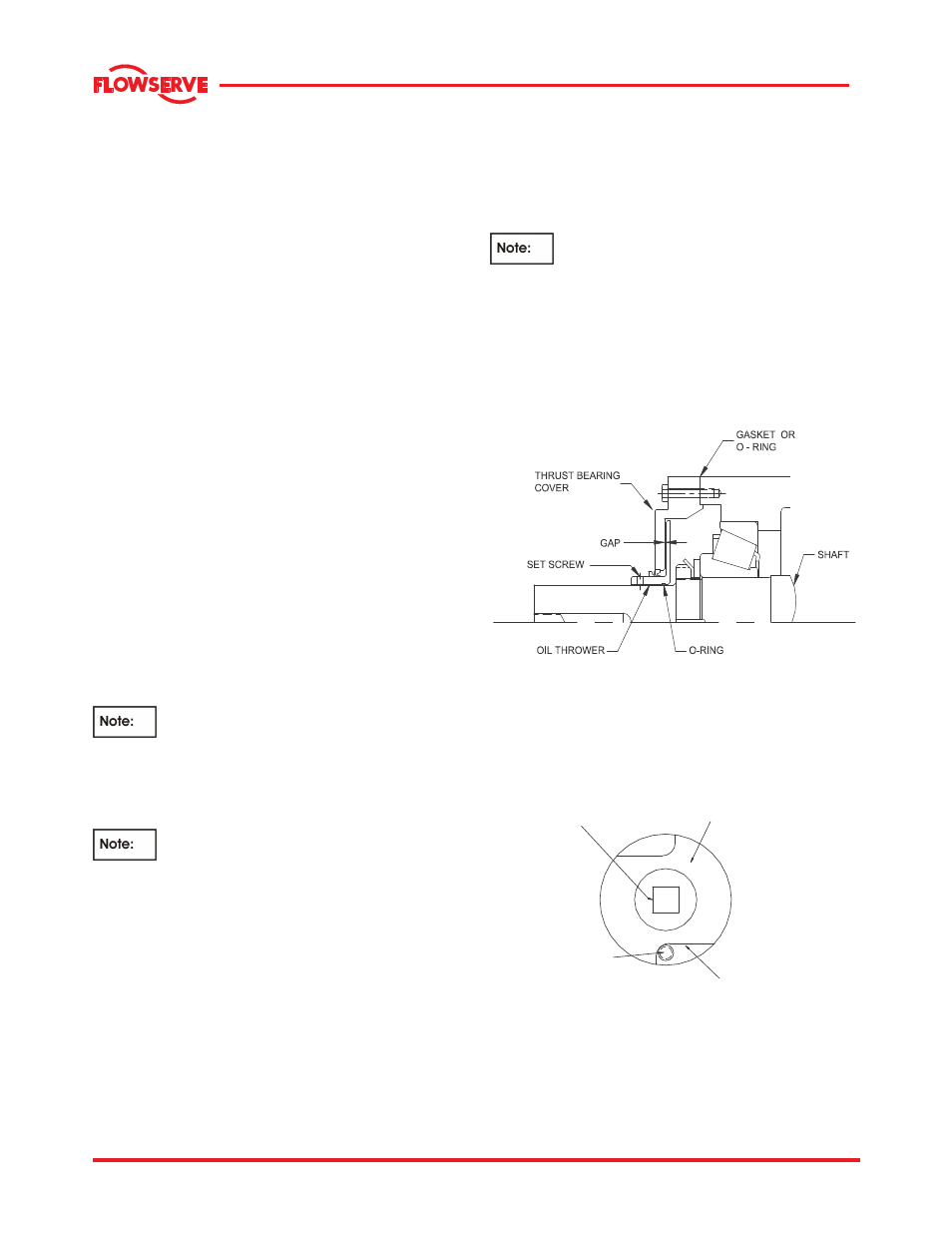
h) Install the thrust bearing oil thrower (See 6.9.1.1)
with its O-ring, inner seal, and thrust bearing
cover with gasket (O-ring for the 7H, 8H, and
8HA bearing frames).
i) Adjust the gap by pulling the thrower up to the
cover and scribing a line on the pump shaft.
j)
Push the oil thrower in 1.0 mm to 1.5 mm (0.040
in. to 0.060 in.) to set the gap.
k)
Tighten the setscrews to secure the oil thrower to
the shaft
.
Grease all the seal lips before installation.
Position the outside seals (line and thrust bearing)
with minimum lip contact to the covers. Excessive lip
pressure will result in the seal running hot and
premature seal failure.
6.9.1.1 oil thrower assembled
6.9.1.2 Impeller nut
IMPELLER NUT
FILLET
(2 PLACES 18O°APART)
IMPELLER NUT
LOCATION FOR
SQUARE BAR
IMPELLER NUT
SET SCREW