7 barrier fluid piping plans – Flowserve SLM-6200 User Manual
Page 10
10
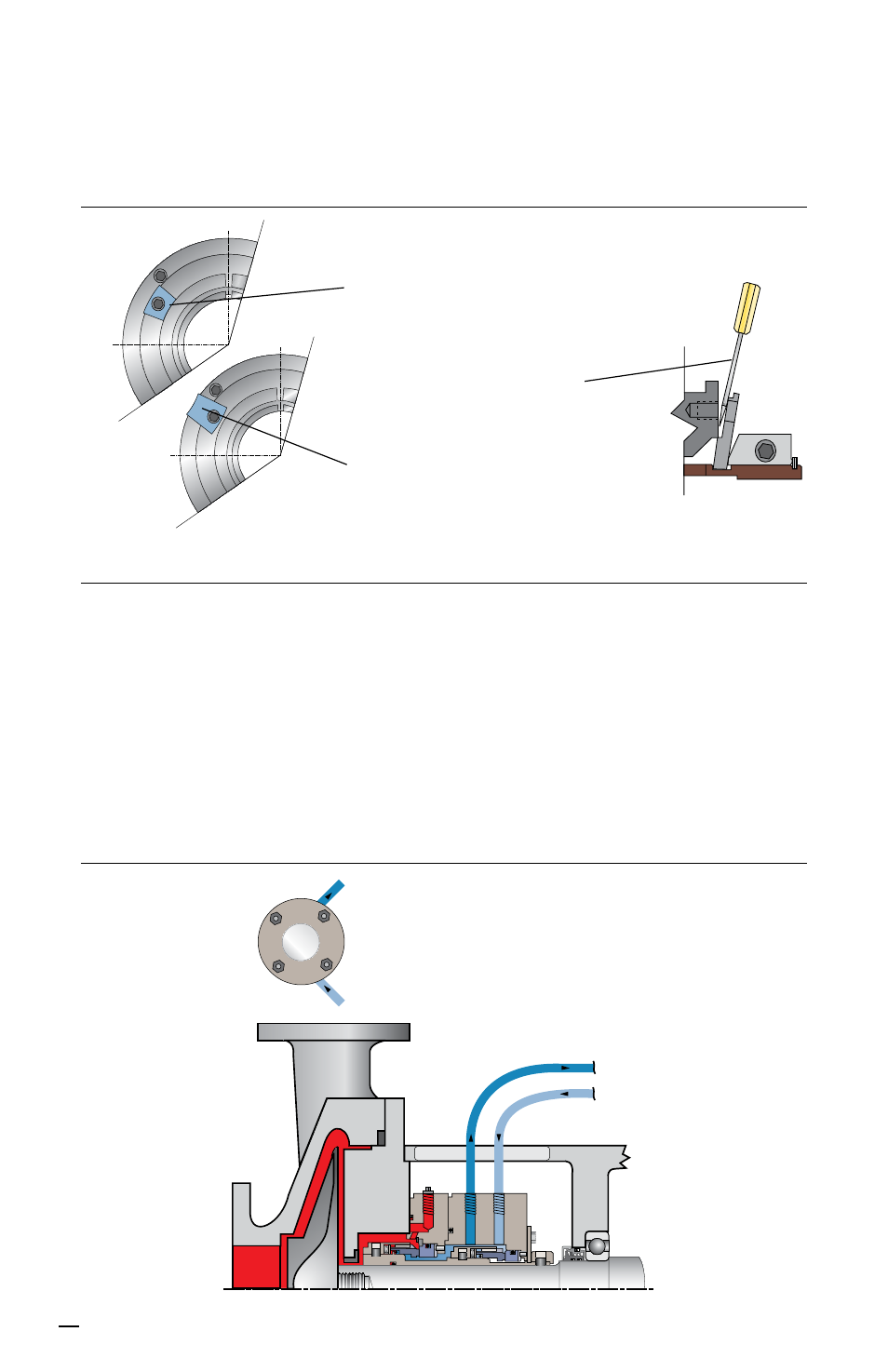
6.2 Remove the setting plate screws. With a screwdriver, pry the setting plates clear of
the gland and remove them. Keep the setting plates and screws with the seal at all
times. See Figure 15.
7 Barrier Fluid Piping Plans
7.1 Typical installation for a Plan 54 support system, pressurized water barrier fluid
circulation by external system. See Figure 16.
See Flowserve Piping Plan Guide FTA160 or your local Flowserve representative for
best practice guidelines for installation of Plans 53A, 53B or 53C.
Note: The SLM-6200 has been designed to leak water barrier fluid into the process
at 4 liters (1 gallon) per day. Barrier fluid must be compatable and able to be refilled
while pressurized. If another barrier fluid is used leakage will increase.
Centering/Setting plate shown in
the stored position for equipment
operation.
Centering/setting plate shown in the
installed position for shipping, seal
installation and maintenance.
A screwdriver is used to lever
the centering/setting plate out.
Setting Plate Removal Figure 15
Plan 54 Figure 16
barrier inlet
barrier outlet
BO
BI
seal
end view