3 general instructions, Center adapter plate to shaft figure 5 – Flowserve SLM-6200 User Manual
Page 4
4
2.6 Ensure that the shaft or shaft sleeve has a 1.6 mm (0.06 inch) x 30° chamfer on the
leading edge to prevent O-ring damage at seal installation.
2.7 Hardened shaft sleeves must not be used when cartridge sleeve locking is
accomplished by set screws bearing directly into the shaft sleeve. Any of the sleeve
collars that clamp the cartridge sleeve to the shaft sleeve may be used on hardened
shaft sleeves.
3 General Instructions
3.1 Ensure that the bearing assembly is mounted correctly (central and square) to the
pump pedestal and securely fastened.
3.2 Ensure that all fit locations on the pedestal are clean and free of burrs.
3.3 Clean the pump shaft/sleeve surface, making sure it is clean of product and rust and
has no burrs.
3.4 If the pump design requires it, bolt seal adapter plate to equipment case/pedestal
(hand tighten only).
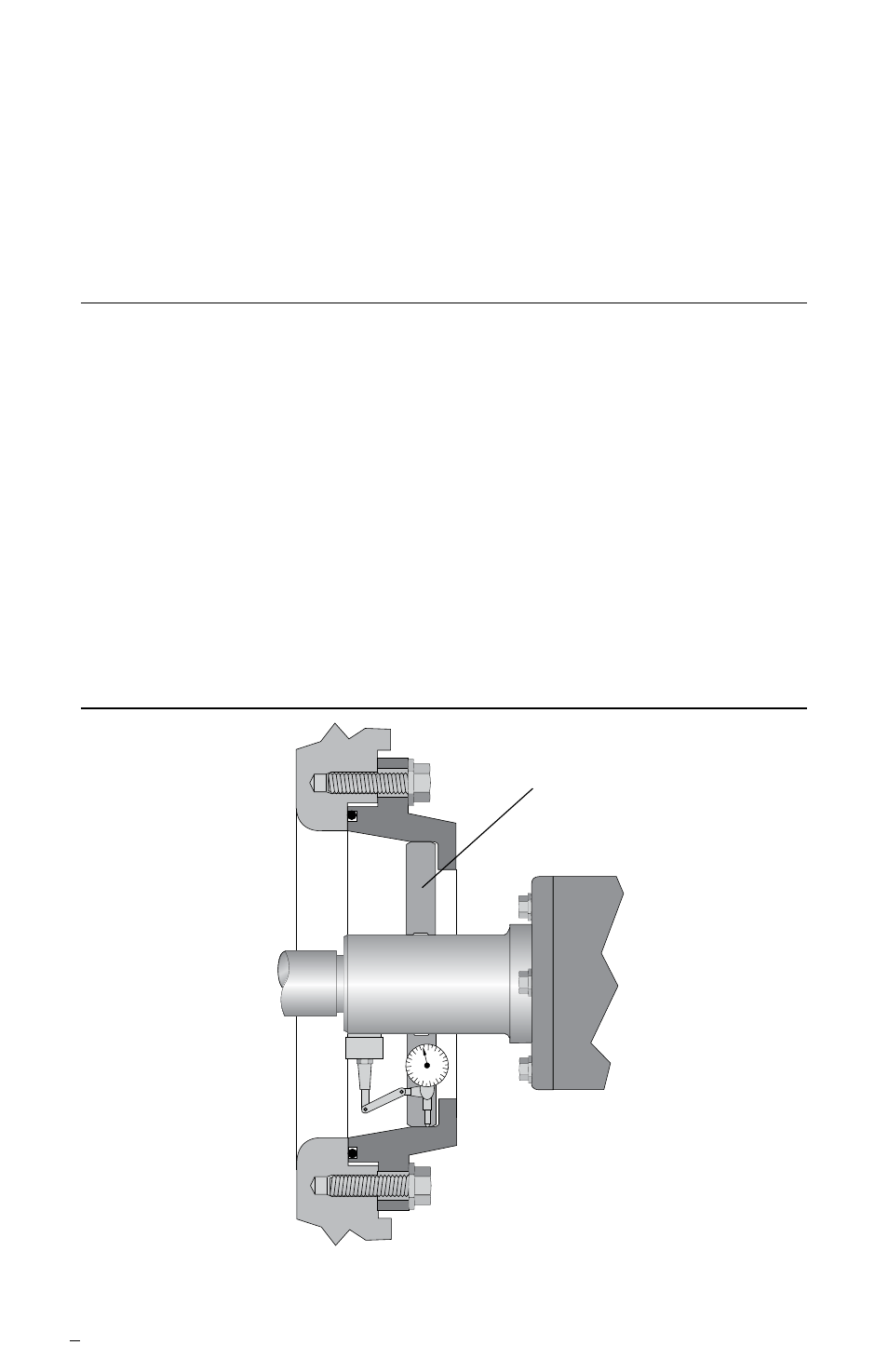
3.5 Locate the seal fit of the adapter to the shaft by use of a dial indicator or centering jig.
The equipment shaft must be concentric to the seal adapter bore to within 0.38 mm
(0.015 inch). See Figure 5.
Center Adapter Plate to Shaft
Figure 5
Centering Jig
Adapter to be Concentric
with Shaft within 0.38 mm
(0.015 inch)