Inserting cartridge figure 13, Check seal chamber face runout figure 12 – Flowserve SLM-6200 User Manual
Page 8
8
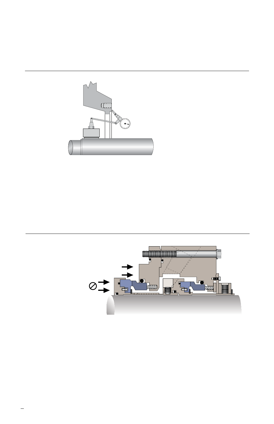
5.3 With the seal clamp collar facing toward the bearing assembly, slide the complete
cartridge over the pump shaft/sleeve and push back toward the bearing housing. See
Figure 13. If the gland screws are too long to insert with the cartridge in place, insert
them through the gland before sliding the cartridge fully onto the shaft.
5.4 If the seal is mounted directly on the shaft, rather than on the equipment sleeve,
install the impeller spacer sleeve (possibly modified).
5.5 Position and lightly secure the equipment casing in place. Do not secure the gland
retaining screws to the equipment casing at this time.
5.6 Check the orientation of the gland ports and reposition as necessary. See Figure 6.
5.7 Install the impeller and suction cover.
5.8 Make any necessary impeller adjustments.
Inserting Cartridge Figure 13
Push on Gland to Slide
the Seal Over the Shaft
Do Not Hammer or
Push on Seal Sleeve
Check Seal Chamber Face Runout Figure 12
Maximum Acceptable Runout
0.001 mm per mm (0.001 inch
per inch) of indicated diameter
5.2 Seal mounting runout (perpendicularity) should be less than 0.001 mm per mm
(0.001 inch per inch) of indicated diameter. See Figure 12. When the equipment case
and shaft are properly aligned, secure the case in place.