5 dry-side (bearing-side) installation – Flowserve SLM-6200 User Manual
Page 7
7
4.7 Check the orientation of the gland ports and reposition as necessary. See Figure 6.
4.8 Insert the retaining screws through the rear face of the pump case and screw into the
seal gland. Tighten the retaining screws evenly to pull the seal into the pump case.
See Figure 10.
5 Dry-Side (Bearing-Side) Installation
The following steps describe installation of the seal cartridge mounted on the dry, or
bearing side of the equipment case. If your cartridge is designed to mount on the wet, or
impeller side of the equipment case, refer to section 4. If you have completed section 4,
skip to section 6.
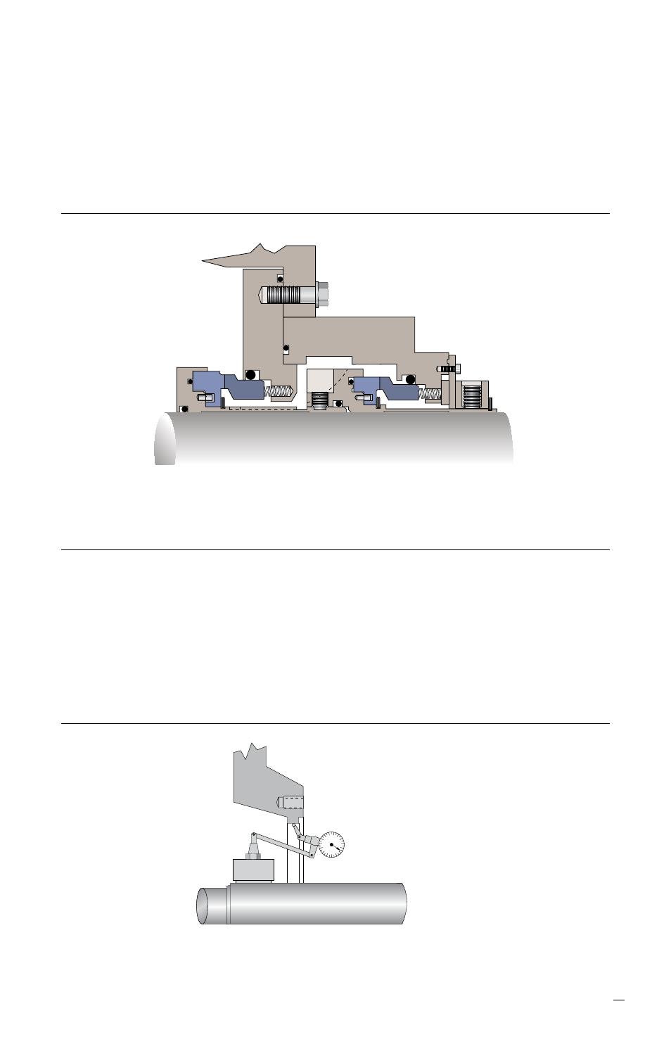
Cartridge in Place (Wet Side) Figure 10
Check Seal Chamber Concentricity
Figure 11
0.38 mm (0.015 inch)
Maximum Seal Chamber
Concentricity Runout
5.1 Seal chamber concentricity should be less than 0.38 mm (0.015 inch). Poor shaft
alignment can reduce seal life. See Figure 11.