4 wet-side (impeller-side) installation, Barrier port orientation figure 6, Check seal chamber face runout figure 7 – Flowserve SLM-6200 User Manual
Page 5
5
3.6 For adapters provided with a centering jig, simply insert the centering jig into the
adapter and tighten adapter bolts, alternately adjusting the cover location until the
centering jig can be removed by hand.
3.7 Apply a light coat of O-ring lubricant to the seal sleeve O-ring. (Silicone grease must
be used with EPDM gaskets.)
Warning:
Do not apply anti-seize or other lubrication to the pump shaft/sleeve. Keep
the shaft/sleeve clean and dry. The use of lubricants will cause improper clamping
pressure by the clamp collar.
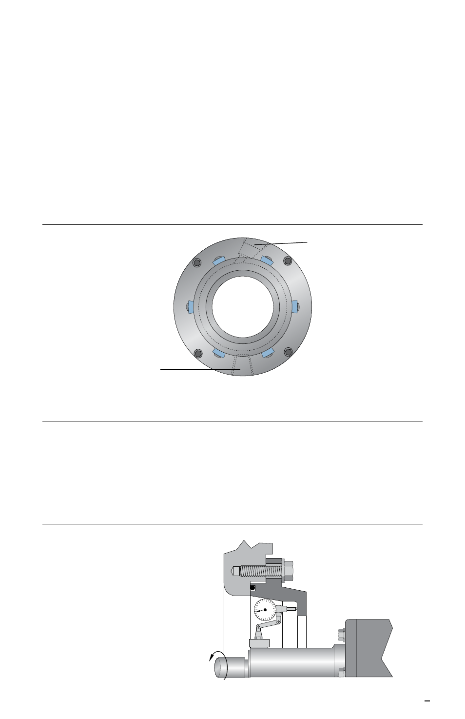
3.8 Orient the barrier inlet and outlet ports as illustrated. See Figure 6. If the ports are not
located 180° apart, position the outlet port at top dead center or as near to that as
possible.
Barrier Port Orientation
Figure 6
Barrier Outlet
Barrier Inlet
4 Wet-Side (Impeller-Side) Installation
The following steps describe installation of the seal cartridge mounted on the wet, or
impeller, side of the equipment case. If your cartridge is designed to mount on the dry, or
bearing, side of the equipment case, skip to section 5.
4.1 Seal chamber face runout (perpendicularity) should be less than 0.001 mm per mm
(0.001 inch per inch) of indicated diameter. See Figure 7.
Check Seal Chamber Face Runout Figure 7
Maximum Acceptable
Runout 0.001 mm per mm
(0.001inch per inch)
of indicated diameter