5 bolting torque values – Flowserve Double-Disc Gate Valve Sizes 2.5 User Manual
Page 10
Anchor/Darling Double Disc Type Gate Valves FCD ADENIM0003-01 - 07/14
10
set of packing. There are holes drilled in the top of the lantern
ring to accommodate the packing hook. For valves with a 3
3/8” or larger diameter stem (5/8” and larger width packing) the
drilled holes are threaded to accept a ¼ - 20 threaded rod. Do not
scratch the stem during these operations.
10. Clean the packing bore in the bonnet to remove residual packing
and other foreign substances. Inspect the bore to insure it is
clean, not damaged and has a surface finish of 125 RMS or better.
11. Install new rings one at a time in the sequence shown on the valve
assembly drawing, being careful to insure the top and bottom
rings are the braided end rings. The ends of the rings should butt
together; no gap or overlap. Install the rings with the butt joints
offset 180° from each other. Push each ring firmly in place with
a packing iron (Fig. 9), Chesterton tamping tool or similar device.
When packing double packing boxes with leak-off, it is essential
that sufficient rings of lower packing be installed to position the
lantern ring at the level of the leak-off.
12. When the stuffing box is full, tighten the gland nuts evenly to
ensure the gland is concentric with the stem. Cocking of the gland
flange can cause binding and scoring of the stem... Suggested
13. gland bolt torque values are included in Table 1. For non-standard
packing designs, check the assembly drawing for packing torque
values. If not there, contact Flowserve Engineering.
14. Cycle the valve several times to consolidate the packing and
retorque the gland nuts. Repeat until fully consolidated and
additional tightening is not needed.
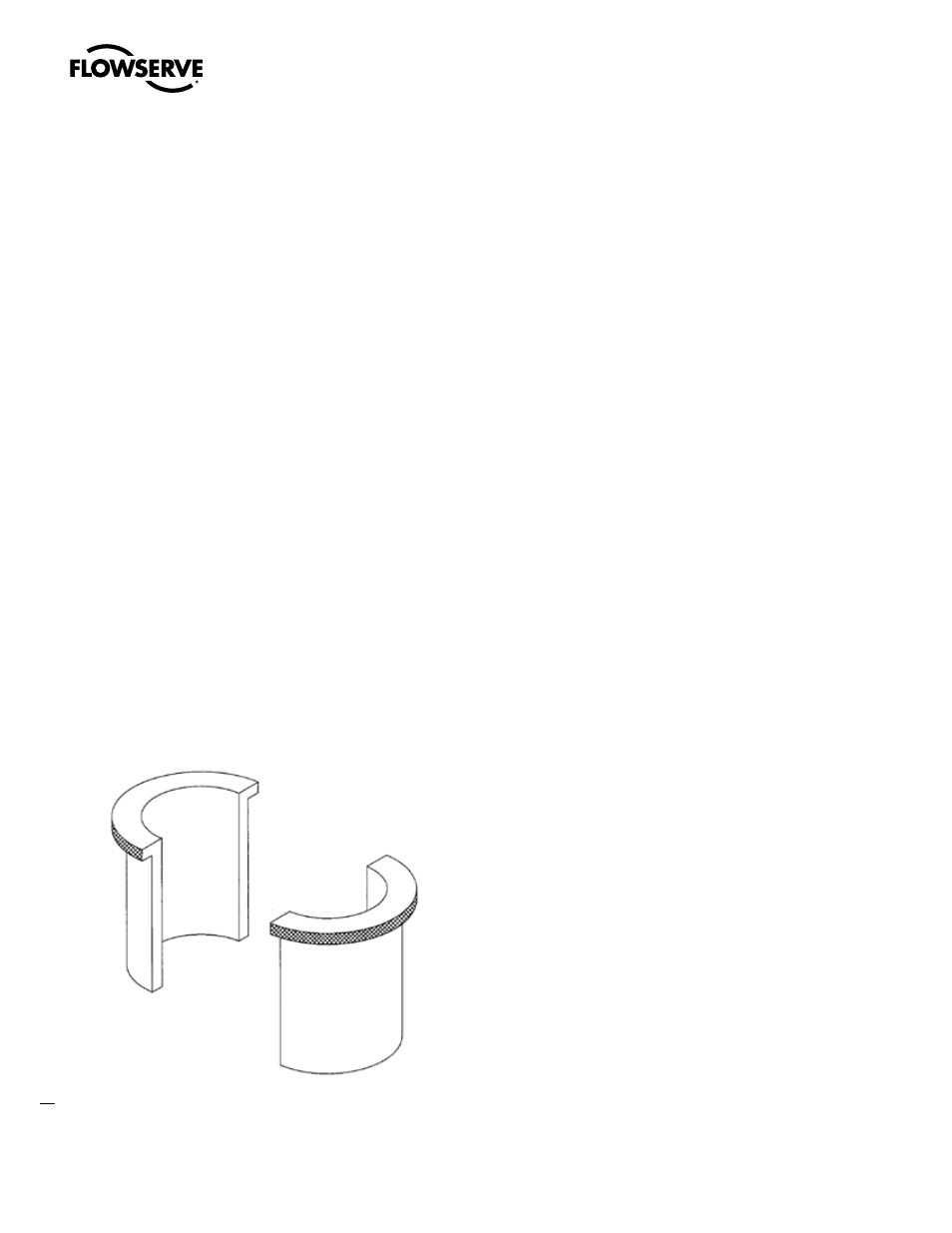
Figure 9 Packing Iron
5.5 Bolting torque values
At regular intervals, check the tightness of all bolting. Bolted bonnet
valves should have the body-bonnet bolting torque to the values shown
in Table 2. Packing glands should be torqued to the values shown in
Table 1. Pressure Seal bonnet bolting should be torqued to the values
show in Table 3. All other bolting should be torqued to the values
shown in Table 4.
1. Torque values specified on certified assembly drawings always
superceded this manual.
2. The maximum torque values are provided for guidance in field
work where higher torques may be required because of material
conditions such as rust and oxides.