2 gear actuators, 3 electric motor actuators, 2 bonnet removal – flanged joint – Flowserve Double-Disc Gate Valve Sizes 2.5 User Manual
Page 18
Anchor/Darling Double Disc Type Gate Valves FCD ADENIM0003-01 - 07/14
18
6.1.1 Handwheels: On handwheel actuated valves (Fig. 10) the
handwheel can be removed by removing the retaining ring (261)
and pulling the handwheel (136) off the yoke sleeve (017). Care
should be taken not to lose the handwheel keys (135).
NOTE: If desired, the yoke and handwheel assembly may be
separated from the valve in one piece. Once the yoke-bonnet
fasteners are removed, the entire assembly can be raised off the
stem by turning the handwheel while the yoke is held stationary.
If further disassembly of the handwheel mechanism is required,
the yoke cap capscrews (228 and the yoke cap (019) must
be removed first. Then the thrust bearing (352) and the yoke
sleeve (017) can be lifted out of the yoke.
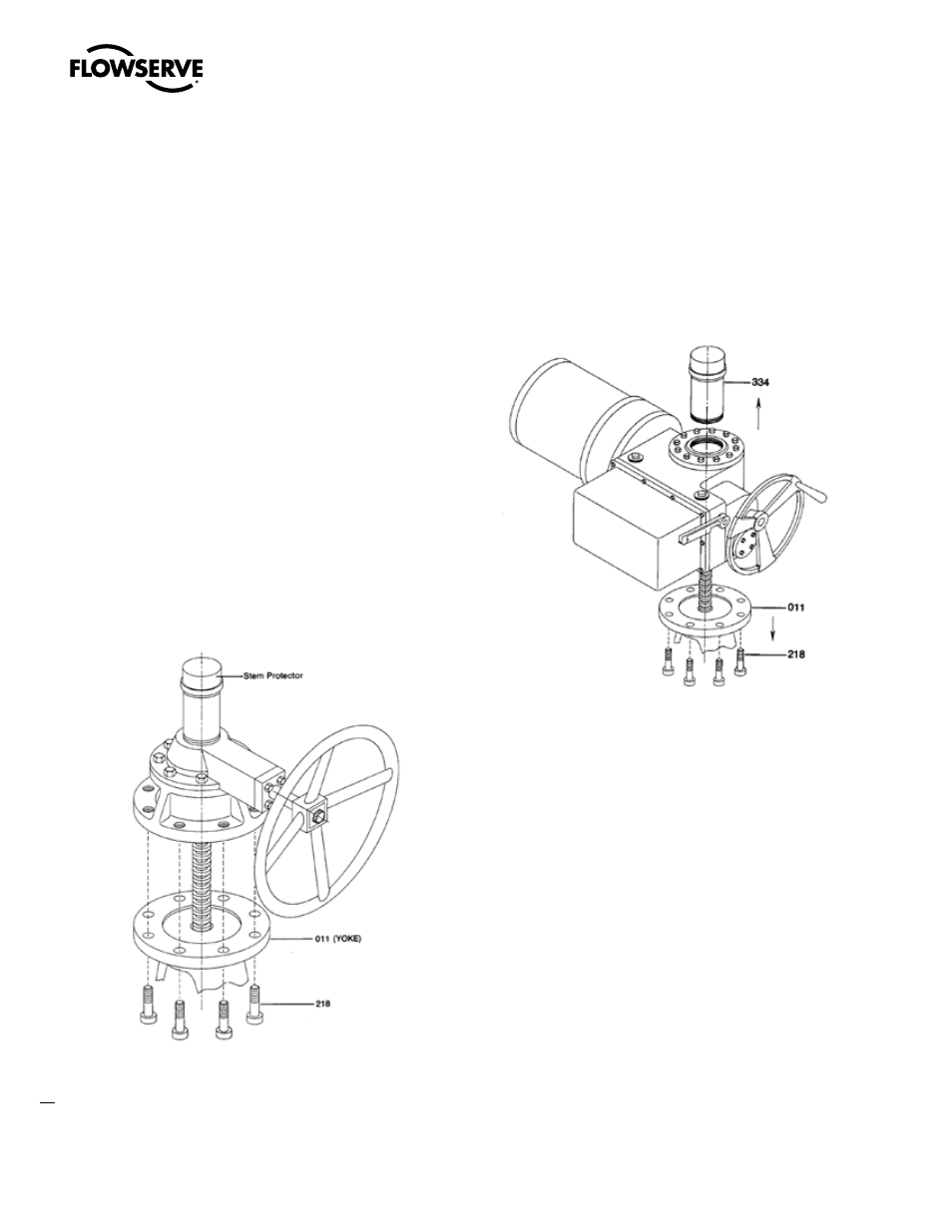
6.1.2 Gear Actuators
Gear actuators (Fig. 11.) are supplied as self-contained units that can be
separated from the yoke by removing the actuator capscrews (218). If
a stem protector is provided it should be removed. With the actuator
properly supported, it may be raised off the yoke either by turning the
handwheel or rotating the entire unit.
Figure 11
6.1.3 Electric Motor Actuators
Although various types of electric motor actuators (Fig. 12) are
supplied, all follow the same pattern for their removal from the valve.
Prior to removal, all power and control wiring should be disconnected
from the actuator. With the stem protector (334) and capscrews (218)
removed, and the actuator properly supported, it can be raised in the
same manner as the gear unit.
Figure 12
6.2 Bonnet Removal – Flanged Joint
6.2.1 Remove the gland nuts (234), the capscrews (217)/yoke studs
(201), and yoke nuts (231) holding the yoke (011) to the bonnet
(002). The yoke, gland flange and gland may now be lifted off
the bonnet. Be careful to not damage the stem (See Fig. 13).
For appropriate yoke configuration, reference customer certified
assembly drawing.
6.2.2 Remove the packing per the instructions in 5.4.
6.2.3 Remove the nuts (230) from the bonnet studs (200). If the
bonnet is too heavy to lift by hand, utilize a hoist with choker
around the bonnet neck or two eye-bolts in the yoke bolt holes.
Lift the bonnet clear of the valve body and stem. Remove the
spiral-wound gasket (100) from its groove. This operation may
require the use of a screwdriver or similar tool to pry the gasket
from the groove. Be careful not to scratch the gasket seating
surfaces.