2 wedges, 3 stem, 4 body – Flowserve Double-Disc Gate Valve Sizes 2.5 User Manual
Page 24
Anchor/Darling Double Disc Type Gate Valves FCD ADENIM0003-01 - 07/14
24
conditions, Flowserve recommends that parts be re-hardfaced or
replaced when the hardfacing thickness is less than 1/16” thick.
e) Visually inspect the trunnion on the back side of the disc for
evidence of distortion or excessive wear. These are symptoms of a
problem other than expected wear. Contact Flowserve engineering
for assistance.
f) Visually inspect the balance of the disc for signs of erosion,
cavitation, material failure or other suspect conditions.
7.2 WEDGES
a) Visually inspect the wedge angle contact points on both the upper
and lower wedges to assure they are smooth and not deformed.
Also inspect the feet on the bottom of the lower wedge for deforma-
tion and the entire wedges for signs of material failure or distortion.
All these are symptoms of over torquing the valve.
b) Visually inspect the disc trunnion hole in the upper wedge for
excessive wear or distortion. Evidence of galling or an out-of-round
condition are abnormal and the cause should be determined and
corrected. Contact Flowserve Field Service for assistance if needed.
7.3 STEM
a) Visually inspect the stem for scratches or galling, particularly in
the area that goes through the packing bore. Machine or polish as
necessary to achieve a 32 finish. If the stem diameter is reduced,
contact Flowserve engineering to determine if the existing packing
design is still adequate.
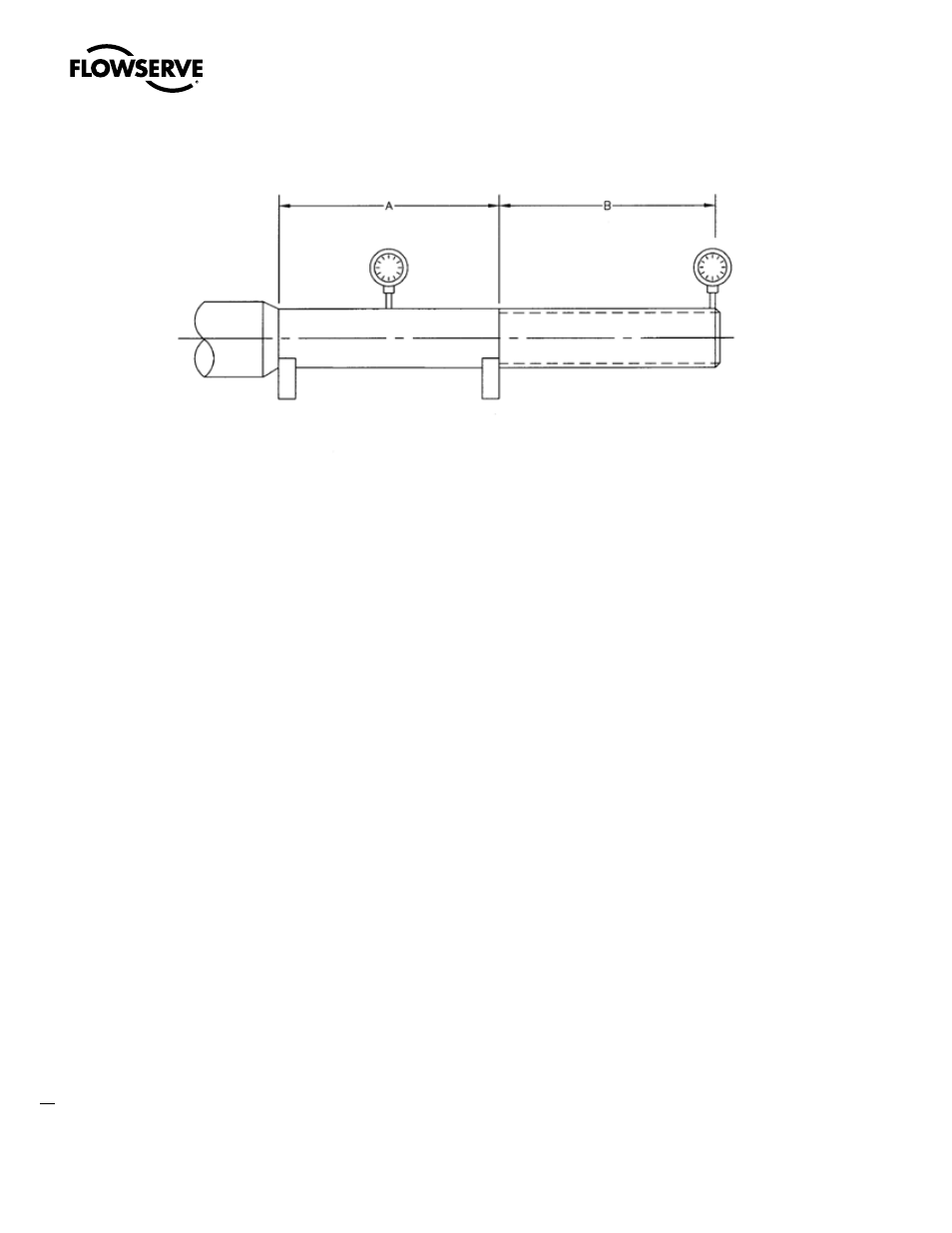
b) Inspect the stem for straightness using the set-up shown in Fig. 20
and measuring the total indicator runout (TIR) at three locations
in both the A and B areas. The TIR should not exceed 0.0005 in/
inch of length of unthreaded area or 0.002 in/inch of length of the
threaded area.
c) Visually inspect the backseat area for damage. It should have a 63
RMS finish.
7.4 Body
a) Inspect the seat ring seating surfaces as specified for discs, Para.
7.1(a), (b), (c) and (d). For step (d), it is acceptable to use one of
the discs for the bluing plate after the disc has been reworked to
an acceptable condition (see 5.6). In the event seat rings must be
replaced, consult Flowserve Field Service.
b) For bolted bonnet designs, clean and inspect the gasket groove.
Any radial scratches or other damage in the bottom of the groove
will create a leak path and should be corrected prior to reassembly.
c) For pressure seal designs, inspect the bore of the body where the
pressure seal gasket is located. The finish requirement is 63 RMS
with no scratches, nicks, blends, etc. in the sealing area. Repairs to
the pressure seal area should not be attempted without consulting
Flowserve Field Service. NOTE: Converting from a metal pressure
seal gasket to a graphite gasket will require a new spacer rings
designed to accommodate the gasket compression.
d) Visually inspect the inside of the valve, especially around the seat
rings for signs of cavitation or erosion. Also check the feet at the
bottom of the body between the seats for any deformation from the
lower wedge. All these conditions are considered abnormal and
Figure 20