0 disassembly, 6 refinishing sealing surfaces, 1 actuator removal – Flowserve Double-Disc Gate Valve Sizes 2.5 User Manual
Page 16
Anchor/Darling Double Disc Type Gate Valves FCD ADENIM0003-01 - 07/14
16
5.6 Refinishing sealing surfaces
Minor discontinuities in both the disc and seat sealing surfaces, which
may cause leakage, can, in many cases, be removed by lapping.
Major defects such as cracks or deep gouges will generally require
replacement of the part.
NOTE: Lapping is a polishing process in which a sealing surface is
ground with an abrasive held in place by a special fixture.
The abrasive is commonly found in paste form or bonded to
a paper backing. Detailed instructions on the use of lapping
abrasives and fixtures, normally supplied with such equip-
ment, should be adhered to.
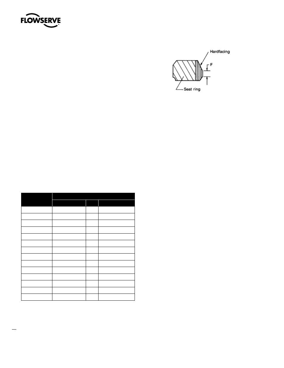
Anchor/Darling gate valves are supplied with a crowned sealing
surface on the seat in order to provide precise seat width and tight
sealing. Lapping of the seat will cause the sealing band width to be
significantly increased. Subsequent to all seat refinishing operations,
the seat width must be reduced to the dimension supplied on the
valve assembly drawing. If seat widths are not on the drawing, use
the nominal dimensions in Table 5. After refinishing seats, check and
adjust the disc pack as necessary per 8.1.1. Failure to do so may
create leakage problems, particularly at lower pressures.
Valve
Size
F
600#
900#
1500#
2 1/2
.090
.090
.125
3
.090
.090
.125
4
.090
.090
.156
6
.125
.125
.187
8
.125
.156
.218
10
.156
.156
.250
12
.156
.187
.250
14
.156
.187
.250
16
.187
.218
.281
18
.187
.218
.312
20
.187
.218
.312
22
.187
.218
.312
24
.187
.218
.312
24
.187
.218
.312
Lapping may also change the distance between the seats. See Para-
graph 8.1.1 for a description of checking and adjustments.
6.0 Disassembly
By carefully following these instructions any Flowserve valve can be
easily disassembled and reassembled. If problems are encountered
with equipment, Flowserve Field Service should be contacted. The
use of improper tools or methods may cause severe damage to the
valve and may void the warranty.
Prior to attempting disassembly of a particular valve, the specific
assembly drawing for the valve should be referred to.
6.1 Actuator removal
Valves are supplied with a wide variety of actuating mechanisms. The
degree of difficulty involved in their removal varies significantly. Sim-
ple bolt-on units such as handwheels, gear units and electric motor
units are fairly commonplace. Their removal only requires the use of
good mechanical practice. More complex pneumatic and hydraulic
units may require specialized skills. Their removal and disassem-
bly should only be attempted by trained personnel. More detailed
information on special actuators will be provided in a separate manual
when applicable. The following general guidelines are provided for
information:
1. Before any attempt to remove the actuator is made, personnel
should verify that the system is depressurized and drained.
2. The valve should then be cycled partially to remove any trapped
pressure and to insure that the disc pack is not stuck in the seat.
3. The disc pack should then be gently lowered into the seat.
For 150# and 300# Class valves: F=3/32”