5 control drawing, Transmitter board options – Flowserve PMV D20 User Manual
Page 11
11
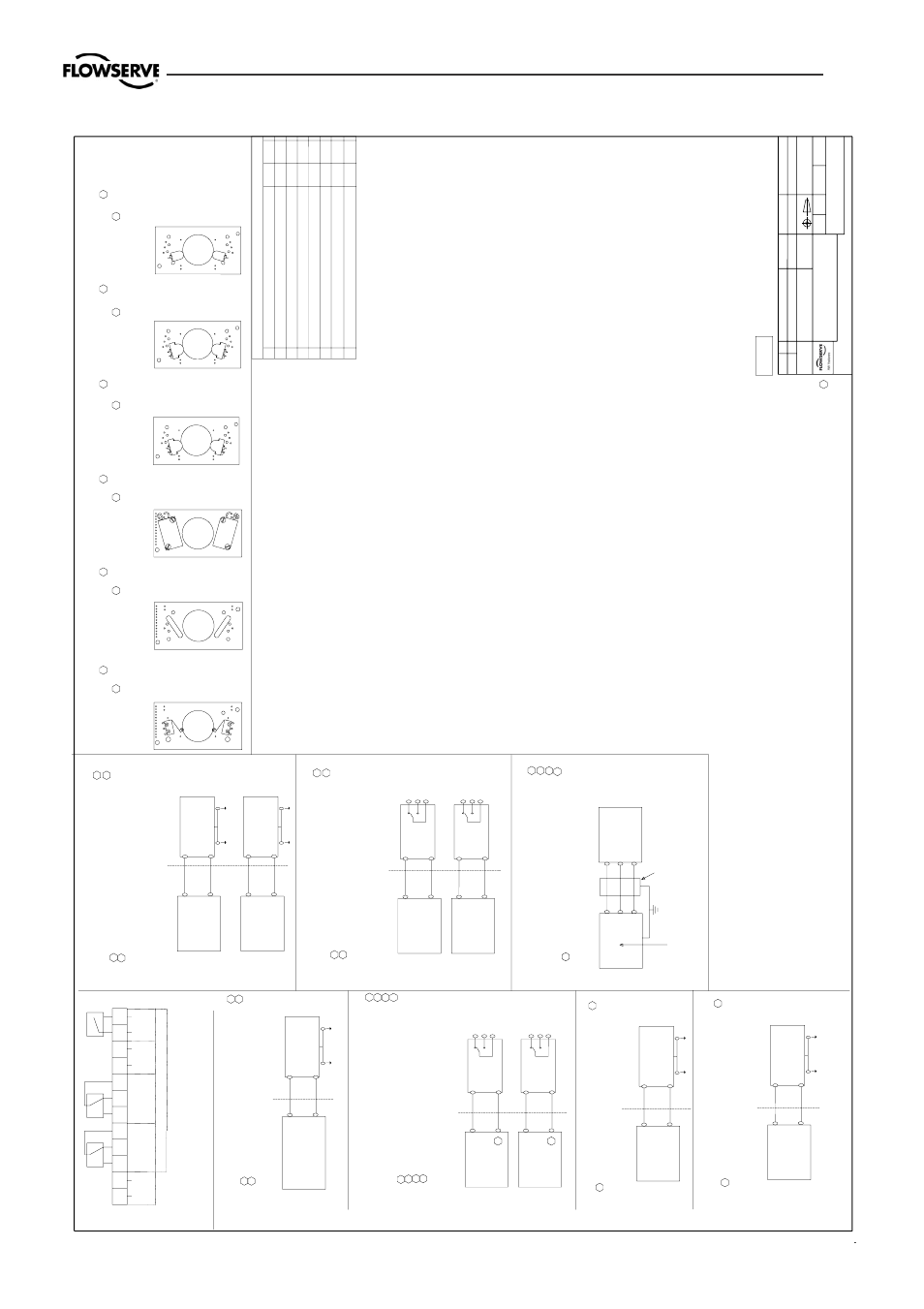
4.5 Control Drawing
UNCL
ASSI
FI
ED AREA
Is
o
lat
or
Is
o
lat
or
4+
Post
it
ioner
Ii : 29,7mA
Pi
: 79mW
Ci
: 40 nF
Ui
: 10,6V
HAZARDEOUS AREA
7+
6-
Posi
ti
oner
Ui
: 10,6V
Pi
: 79mW
Ci
: 40 nF
Li : 100 µ
H
Ii : 29,7mA
HAZARDEOUS AREA
3-
Li : 100 µ
H
Pi
n 3;
4 :
Swi
tch 1
Pi
n 6;
7 :
Swi
tch 2
UNCL
ASSI
FI
ED AREA
Pi
: 653mW
D2xI
xx-xxxxxx-xxTxx
Posi
ti
oner
Model
no:
D3I
xx-xxxxxx-
xxTx/
Logi
x 8xx-02-xxxxxx-xxx
-xxT
Pi
n 9;
10
4-20 mA
O
u
tput
UNCL
ASSI
FI
ED AREA
HAZARDEOUS AREA
Sa
fe
ty
Ba
rrie
r
/P
A
/P
A
10-
Ii : 93mA
Ui
: 28V
Li : 11,3 µ
H
Ci
: 16,4 nF
9+
Ci
: 5,64 nF
D2xI
xx-xxxxx-xxTxx
Posi
ti
oner
Model
no:
D3I
xx-xxxxxx-
xxTx/
Logi
x 8xx-02-xxxxxx-xxx
-xxT
Al
a
rm
Pi
n 11;
12
/P
A
/P
A
11+
12-
UNCL
ASSI
FI
ED AREA
Sa
fe
ty
Ba
rrie
r
Ui
: 28V
Pi
: 315mW
Ii : 45mA
Li : 11,3 µ
H
HAZARDEOUS AREA
Pi
: 315mW
Posi
ti
oner
Posi
ti
oner
N
o
rm
a
lly
Cl
osed
Pi
n 7;
8 :
Swi
tch 2
Pi
n 4;
5 :
Swi
tch 1
Sa
fe
ty
Ba
rrie
r
3 or 4
5
Pi
n 3;
5 :
Swi
tch 1
Pi
n 6;
8 :
Swi
tch 2
Norma
lly
O
p
e
n
UNCL
ASSI
FI
ED AREA
Ui
: 28V
Ci
: 1 nF
Ii : 45mA
HAZARDEOUS AREA
Pi
: 315mW
/P
A
/P
A
/P
A
/P
A
Sa
fe
ty
Ba
rrie
r
6 or 7
8
UNCL
ASSI
FI
ED AREA
Ui
: 28V
Ci
: 1 nF
Ii : 45mA
Li : 1 µ
H
HAZARDEOUS AREA
Li : 1 µ
H
UNCL
ASSI
FI
ED AREA
Posi
ti
oner
Posi
ti
oner
Pi
n 7;
8 :
Swi
tch 2
Pi
n 4;
5 :
Swi
tch 1
N
o
rm
a
lly
Cl
osed
Pi
n 6;
8 :
Swi
tch 2
Pi
n 3;
5 :
Swi
tch 1
Norma
lly
O
p
e
n
Is
o
lat
or
Is
o
lat
or
3 or 4
Ui
: 10,6V
HAZARDEOUS AREA
5
8
6 or 7
Pi
: 79mW
Ci
: 1 nF
Li : 1 µ
H
Ui
: 10,6V
Ii : 29,7mA
Ci
: 1 nF
Li : 1 µ
H
Pi
: 79mW
HAZARDEOUS AREA
Ii : 29,7mA
UNCL
ASSI
FI
ED AREA
4
Re
mo
te
unit output parameter
Po
: 0,38W
Posi
ti
oner
Sh
ielded cable less than 10 metres
HAZARDEOUS AREA
It is
o
n
ly
a
llo
w
e
d
to
co
n
n
e
ct th
e P
o
t. un
it to
th
e
posi
ti
oner
s connector
s 3,
4 a
nd 5.
T
h
e
co
n
n
e
ctio
n
r
equir
es a
sh
ield
ed
ca
ble less th
a
n
10
me
tr
e
s o
r le
ss tha
n
30 feet.
Pot.
Pi
n 3;
4;
5
4
3
5
5
3
D3
Ixx-xxxxxx-xx6x
D2
xIxx-xxxxxx-xx6xx
D2
xIxx-xxxxxx-xx5xx
D2
xIxx-xxxxxx-xx4xx
D2
xIxx-xxxxxx-xxN
xx
D2
xIxx-xxxxxx-xxPxx
D2
xIxx-xxxxxx-xxSxx
Rem
ove cover and innercover(see m
a
nu
al), visu
ally v
erify
T
ra
n
sm
itter Boa
rd op
tion.
4-20 m
A
O
u
tput
Me
c
h
ani
c
al
S
w
.
Transmitter Board Options
3-A
s81M
3
-A
s81N
3-A
s81P
All components need Saftey Barriers * except the Swi
tches on transmitter board 3-As81N, 3-As81D4,
Explosion Hazard - Do not disconnect equipment unles
s area is known to be non-hazardous.
Substitution of the following components may impair su
itability for Division 2 :
or; read, understand and adhere to the manufacturer'
s live maintenance procedures.
To prevent ignition of flammable or combustible atmosph
eres, disconnect power before servicing,
*Only CSA and FM
Substitution of components may impair Intrinsic Safety
.
Warnings:
Non-Incendive:
Further requirements for FM:
- Associated apparatus manufacturer's installation
drawing must be followed when installing this equip
ment.
- The Entity Concept allo
ws interconnections of int
rinsically safe apparatus with associated apparatus
when the following is true:
Vmax or Ui larger than Voc, Vt or Uo;
Imax or Ii larger than Isc, It or Io
Pmax or Pi larger than Po
Ca larger than Ci + Ccable
La larger than Li + Lcable
- Dust-Tight conduit seal must be when installed in
Class II and Class III environments.
- Control equipment connected to Associated Apparat
us must not use or generate more than 250 Vrms or V
dc.
- Resistance between Intrinsically Safe Ground must
be less than 1,0 Ohm.
- Installation should be in accordance with ANSI/IS
A-RP12.06.01 "Installation of Intrinsically Safe Sy
stems for Hazardous (Classified) Locations" and the
National
Electric Code (ANSI/NFPA 70).
- The associated apparatus must be FM approved.
- The associated apparatus must be a resistively li
mited by a single or mult
iple channel FM Approved A
ssociated apparatus having parameters less than tho
se quoted,
and for which the output and the combinations of ou
tput is non-ignition capable
for the Class, Divisio
n and Group of use.
Model
no:
Logix 8xx-
02-
xxxxxx-
xx1-
xxx
4-20 m
A
O
u
tput
Nam
u
r S
w
.
Pr
ox
im
ity
Sw
.
4-20 m
A
O
u
tput
3-A
s81D4
3
-A
s81D5
3
-A
s81D6
Slotted
N
a
m
u
r Sw
.
4-20 m
A
O
u
tput
Slotted
N
a
m
u
r Sw
.
4-20 m
A
O
u
tput
Slotted
N
a
m
u
r Sw
.
4-20 m
A
O
u
tput
D3
Ixx-xxxxxx-xxSx
Model
no:
Logix 8xx-
02-
xxxxxx-
xx2-
xxx
D3
Ixx-xxxxxx-xxPx
Model
no:
Logix 8xx-
02-
xxxxxx-
xx3-
xxx
D3
Ixx-xxxxxx-xxN
x
Model
no:
Logix 8xx-
02-
xxxxxx-
xx4-
xxx
D3
Ixx-xxxxxx-xx4x
Model
no:
Logix 8xx-
02-
xxxxxx-
xx5-
xxx
D3
Ixx-xxxxxx-xx5x
Model
no:
Logix 8xx-
02-
xxxxxx-
xx6-
xxx
3-As81D5, 3-As81D6, 3-As81P, D3-As38E N, D3-As38E D
4, D3-As38E D5, D3-As38E D6 and D3-As38E P.
Pi
n
2: Irtn
Posi
ti
oner
/P
A
Sa
fe
ty
Ba
rrie
r
/P
A
Pi
n 1;
2
1+
2-
HAZARDEOUS AREA
Ui
: 28V
Ii : 93mA
Pi
: 653mW
Ci
: 11,3 nF
Li : 11,3 µ
H
Pi
n
1: Isrc
UNCL
ASSI
FI
ED AREA
RE
V
ISIO
N
S
RE
V
.
D
E
SC
RIPTIO
N
D
ATE
M
O
D
. BY
1
"Ol
d
" T
ransm
itte
r b
o
ar
d a
ssem
b
lie
s (D
3-AS38E) o
m
it
ted
.
Si
n
g
le
a
c
ti
ng r
e
mote
adde
d.
2006-
11-
14
K
B
M
2
11.
3 wa
s 5 (3x);
11.
3 wa
s 4;
16.
4 wa
s 4;
11.
3 wa
s
5;
5.
64 wa
s 5.
7
Rem
o
te
outp
ut p
a
ra
me
te
r adde
d.
2007-
01-
12
K
B
M
3M
ode
l co
d
e
o
f Lo
gi
x 500si
a
d
d
e
d
.
2007-
11-
13
K
B
M
4R
ed
esi
g
ned
2008-
03-
04
JEE
50
c
h
a
n
g
e
t
o
x
in
"Mode
l no" to al
lo
w
p
re
ssur
e
se
ns
or
op
ti
o
n
in
co
d
e
.
2008-
04-
24
MER
6
NAMU
R
swi
tch
es,
L
i: 50
µH
c
h
an
ge
d t
o
Li
: 100
µH
; C
i: 3
5
nF c
h
an
ge
d t
o
Ci
: 40 nF.
2008-
04-
29
MER
7
Doc
u
me
nt name
c
h
ange
d to D3
/D
2
0
. M
ode
l c
ode
f
o
r D2
0
up
gr
ade
d
.
M
ode
lc
ode
f
o
r Logi
x
5
XXs
i de
le
te
d.
2008-
11-
06
MR
n
8. S
w
itch 2 C
O
M
1. Input signal
12. A
larm Output -
11. A
larm Output +
10. 4-20 mA
-
9. 4-20 mA
+
7. S
w
itch 2 N
C
6. S
w
itch 2 N
O
5. S
w
itch 1 C
O
M
4. S
w
itch 1 N
C
3. S
w
itch 1 N
O
2. Input signal
4-20mA input signal
Mechanical or Proximity sw
itches
NAMUR s
w
it
c
h
e
s
D3I
xx-xxxxxx-xx4x/
Logi
x 8xx-02-xxxxxx-xxx-xx4
Model
no:
D3I
xx-xxxxxx-x4xx/
Logi
x 81x-02-xxxxxx-xxx
-xxx
Model
no:
D3I
xx-xxxxxx-
xxNx/
Logi
x 8xx-02-xxxxxx-xxx
-xx3
12
3
4
5
6
7
8
9
1
0
1
1
1
2
-
-
-
1
2
4-
20m
A
ALARM
OUT
OUT
INPUT
OPTI
ON
NO
NC
COM
N
C
NO
COM
SW1
SW2
(REMOTE)
SI
G
NAL
D3I
xx-xxxxxx-x5xx/
Logi
x 82x-02-xxxxxx-xxx-xxx
D3I
xx-xxxxxx-xx5x/
Logi
x 8xx-02-xxxxxx-xxx-xx5
D3I
xx-xxxxxx-xx6x/
Logi
x 8xx-02-xxxxxx-xxx-xx6
Model
no:
D3I
xx-xxxxxx-
xxSx/
Logi
x 8xx-02-xxxxxx-xxx
-xx1
D3I
xx-xxxxxx-xxPx/
Logi
x 8xx-02-xxxxxx-xxx-xx2
Model
no:
D3I
xx-Mxxxxx-xxxx/
Logi
x 8xx-02-xxxxxx-xMx
-xxx
D3I
xx-Pxxxxx-xxxx/
Logi
x
8xx-02-xxxxxx-xPx-xxx
to
th
e
N
o
tif
ie
d
b
o
d
y
D3I
xx-Rxxxxx-xxxx/
Logi
x
8xx-02-xxxxxx-xRx-xxx
D3I
xx-Qxxxxx-xxxx/
Logi
x
8xx-02-xxxxxx-xQx-xxx
D2xI
xx-xxxxxx-x4xxx
D2xI
xx-xxxxxx-xxNxx
D2xI
xx-xxxxxx-xxSxx
D2xI
xx-xxxxxx-x5xxx
D2xI
xx-xxxxxx-xx4xx
D2xI
xx-xxxxxx-xx6xx
D2xI
xx-xxxxxx-xx5xx
D2xI
xx-xxxxxx-xxPxx
D3I
xx-xxxxxx-xxPx/
Logi
x 8xx-02-xxxxxx-xxx-xx2
D2xI
xx-xxxxxx-xxPxx
D2xI
xx-xxxxxx-xxSxx
Model
no:
D3I
xx-xxxxxx-
xxSx/
Logi
x 8xx-02-xxxxxx-xxx
-xx1
Mechanical or Proximity sw
itches
D2xI
xR-xxxxxx-xxxxx
No
m
o
d
if
ic
a
tio
n
p
e
rm
itte
d
w
ith
o
u
t r
e
fe
re
n
c
e
7
Tested according to withstand dielectric strength r
equirement IEC EN 60079-11 6.3.12
Ingress Protection IP 66, NEMA 4X
Sc
he
dul
e
dr
a
w
in
g
5
5
5
5
5
5
5
5
5
5
5
5
5
5
5
5
5
5
5
7
Remote unit
5
5
6
7
5
6
7
7
7
7
7
7
7
7
7
7
7
7
7
7
7
7
7
PALMS
T
IERN
A IN
TERN
ATION
A
L AB
PALMS
T
IERN
A IN
TERN
ATION
A
L AB
PALMS
T
IERN
A IN
TERN
ATION
A
L AB
PALMS
T
IERN
A IN
TERN
ATION
A
L AB
DRA
W
IN
G
NO.
DRA
W
IN
G
NO.
DRA
W
IN
G
NO.
DRA
W
IN
G
NO.
DRW
BY
DRW
BY
DRW
BY
DRW
BY
A
PPR.
BY
A
PPR.
BY
AP
P
R
. B
Y
A
PPR.
BY
S
C
A
L
E
SC
A
L
E
SC
A
L
E
SC
A
L
E
D
AT
E
DA
TE
DA
TE
DA
TE
ANNOT
AT
IO
N
ANNOT
AT
IO
N
ANNOT
AT
IO
N
ANNOT
AT
IO
N
DIME
N
S
IO
N
DIME
N
S
IO
N
DIME
N
S
IO
N
DIME
N
S
IO
N
MA
T
E
RIA
L
MA
T
E
RIA
L
MA
T
E
RIA
L
MA
T
E
RIA
L
DE
SCRIPTIO
N
DE
SCRIPTIO
N
DE
SCRIPTIO
N
DE
SCRIPTIO
N
PCSPCSPCSPCS
PA
RT
NO.
PA
RT N
O
.
PA
RT
NO.
PA
RT N
O
.
HOL
E T
O
L
.
HOL
E T
O
L
.
HOL
E T
O
L
.
HOL
E T
O
L
.
UNS
P
E
C
IF
IED
T
O
L
E
R
ANC
ES
AC
C
O
R
D
ING
T
O
:
UNS
P
E
C
IF
IED
T
O
L
E
R
ANC
ES
AC
C
O
R
D
ING
T
O
:
UNS
P
E
C
IF
IED
T
O
L
E
R
ANC
ES
AC
C
O
R
D
IN
G
T
O
:
UNS
P
E
C
IF
IED
T
O
L
E
R
ANC
ES
AC
C
O
R
D
ING
T
O
:
SU
R
F
A
C
E
SU
R
F
A
C
E
SU
R
F
A
C
E
SU
R
F
A
C
E
PRO
J
E
CTIO
N
E
U
RO
PA
PRO
J
E
CTIO
N
E
U
RO
PA
PRO
J
E
CTIO
N
E
U
RO
PA
PRO
J
E
CTIO
N
E
U
RO
PA
KORT
A GAT
A
N 9
S
E
-1
7
1
5
4
SO
L
N
A
SWED
EN
-
T
e
l:+
46(0)8
555 106 00-
F
a
x
:
+
46(0)8 555 106 01 -
w
w
w
.pm
v
.nu
KORT
A GAT
A
N 9
S
E
-1
7
1
5
4
SO
L
N
A
SWED
EN
-
T
e
l:+
46(0)8
555 106 00-
F
a
x
:
+
46(0)8 555 106 01 -
w
w
w
.pm
v
.nu
KORT
A GAT
A
N 9
S
E
-1
7
1
5
4
SO
L
N
A
SWED
EN
-
T
e
l:+
46(0)8
555 106 00-
F
a
x
:
+
46(0)8 555 106 01 -
w
w
w
.pm
v
.nu
KORT
A GAT
A
N 9
S
E
-1
7
1
5
4
SO
L
N
A
SWED
EN
-
T
e
l:+
46(0)8
555 106 00-
F
a
x
:
+
46(0)8 555 106 01 -
w
w
w
.pm
v
.nu
Contr
o
l Dr
awi
n
g
Contr
o
l Dr
awi
n
g
Cont
ro
l Dr
awi
n
g
Contr
o
l Dr
awi
n
g
----
----
imp
art
ed
to
a thi
rd par
ty nor
be us
ed
fo
r any unaut
horiz
ed
purp
ose
. C
ontra
venti
on wi
ll be
pros
ec
ute
d
imp
art
ed
to
a thi
rd par
ty nor
be us
ed
fo
r any unaut
horiz
ed
purp
ose
. C
ontra
venti
on wi
ll be
pros
ec
ute
d
imp
art
ed
to
a thi
rd par
ty nor
be us
ed
fo
r any unaut
horiz
ed
purp
ose
. C
ontra
venti
on wi
ll be
pros
ec
ute
d
imp
art
ed
to
a thi
rd par
ty nor
be us
ed
fo
r any unaut
horiz
ed
purp
ose
. C
ontra
venti
on wi
ll be
pros
ec
ute
d
3-863-863-863-86
----
----
----
KBMKBMKBMKBM
D3/D20D3/D20D3/D20D3/D20
PMV PositionerPMV PositionerPMV PositionerPMV Positioner
----
----
This
do
cum
en
t m
ust
no
t b
e c
opie
d wi
thout our wr
itte
n perm
is
sion and the
conte
nts
there
of m
us
t not be
This
do
cum
en
t m
ust
not be c
opi
ed
without our
writ
ten pe
rm
is
sion and the
conte
nts
there
of m
us
t not be
This
do
cum
ent m
us
t not be
co
pie
d wi
thout our wr
itte
n perm
is
sion and the
conte
nts
there
of m
us
t not be
This
do
cum
en
t m
ust
no
t b
e c
opie
d wi
thout our wr
itte
n perm
is
sion and the
conte
nts
there
of m
us
t not be
051
208
051
208
051
208
051
208
Always see www.pmv.nu for latest revision.