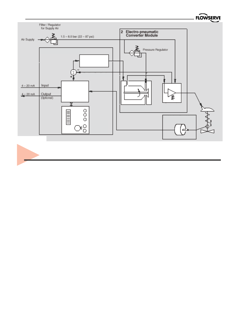
Principle of operation, Figure 1 – Flowserve PMV D20 User Manual
Page 16
16
The PMV D20 positioner is a digital posi-
tioner with various options. The positio-
ner consists of three main modules:
1. The microprocessor-based electronic
control module includes direct local user
interface switches
2. The piezo valve-based electro-
pneumatic converter module
3. The infinite resolution valve position
sensor.
The basic positioner operation is best
understood by referring to figure 1. The
complete control circuit is powered by the
two-wire, 4-20 mA command signal. The
analog 4-20 mA command is passed to
the microprocessor, where it is compared
to the measured valve stem position. The
control algorithm in the processor
performs control calculations and
produces an output command to the
piezo valve, which drives the pneumatic
amplifier. The position of the pilot valve
in the pneumatic amplifier is measured
and relayed to the inner loop control
circuit. This two-stage control provides
for more responsive and tighter control
than is possible with a single stage
control algorithm. The pneumatic
amplifier controls the airflow to the
actuator. The change of pressure and
volume of the air in the actuator causes
the valve to stroke. As the valve
approaches the desired position, the
difference between the commanded po-
sition and the measured position
becomes smaller and the output to the
piezo is decreased. This, in turn, causes
the pilot valve to close and the resulting
flow to decrease, which slows the
actuator movement as it approaches, the
new commanded position. When the
valve actuator is at the desired position.
the pneumatic amplifier output is held at
zero, which holds the valve in a cons-
tant position.
Piezo Valve
Inner Loop
Position feed-
Pneumatic
Stroke
Control
Valve
Local
User
Inner Loop
Piezo Control
Micro-
Processor
3 Valve
1 Digital Control
Gain
5. Principle of operation
Figure 1.