Limit switches & 4 - 20 ma transmitter (optional), 1 general, 2 model selection – Flowserve PMV D20 User Manual
Page 28: 3 priciple of operation, 4 installation
28
10. Limit switches & 4 - 20 mA transmitter (Optional)
Caution!
The installation of electrical
equipment in hazardous areas must
comply with the procedures contained
in the certificates of conformity. Coun-
try specific regulations may apply.
Electrical safety is determined only by
the power supply device.
10.1 General
D20 can be equipped with optional plug
in modules for limit switches and/or 4-20
mA feedback transmitter
10.2 Model selection
See D20 model code
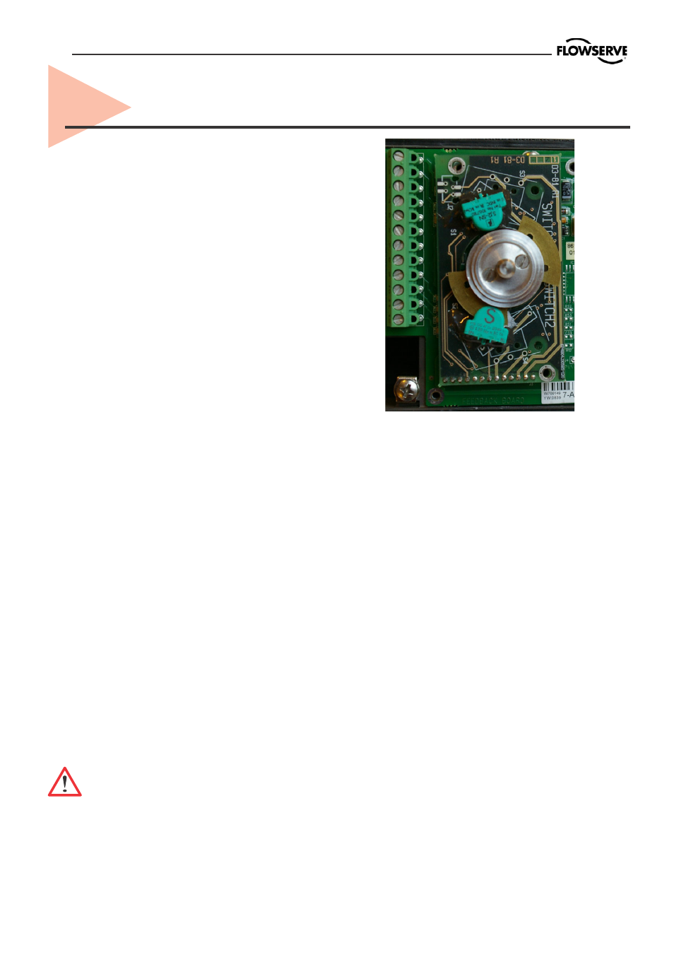
10.3 Priciple of operation
The stroke of the actuator/valve is picked
up by the potentiometer inside the D20.
Movement is transferred from actuator
via lever or shaft coupling. Cams/vanes
mounted on the positioner shaft actuate
limit switches 1 and 2. The switching point
can be adjusted on each cam/vane.
The position transmitter converts actual
position into a 4-20mA output signal. This
loop requires an external 12-25 VDC
power supply.
10.4 Installation
Caution! Turn off power and air
supply before starting the installa-
tion.
Important!
For D20 installed in hazardous areas,
maintenance and repair must only to be
made by authorized and trained staff.
-Remove cover, indicator if present and
inner plastic cover.
-Check that spacers are installed on the
printed circuit board.
-Carefully install feedback board into its
position on the pins.
-Secure it with two (2) screws.
-Install cam assembly on the shaft, if
feedback card has mechanical micro
switches, be careful to not damage
switch arms.
-Install plastic inner cover.
-Adjust cams/vanes to ensure proper
switching.
-Secure cam/van position by locking
them with two (2) screws.
-Calibrate 4-20 mA transmitter, (see next
page).
-Install cover.