Tubing positioner to actuator – Flowserve PMV D20 User Manual
Page 22
22
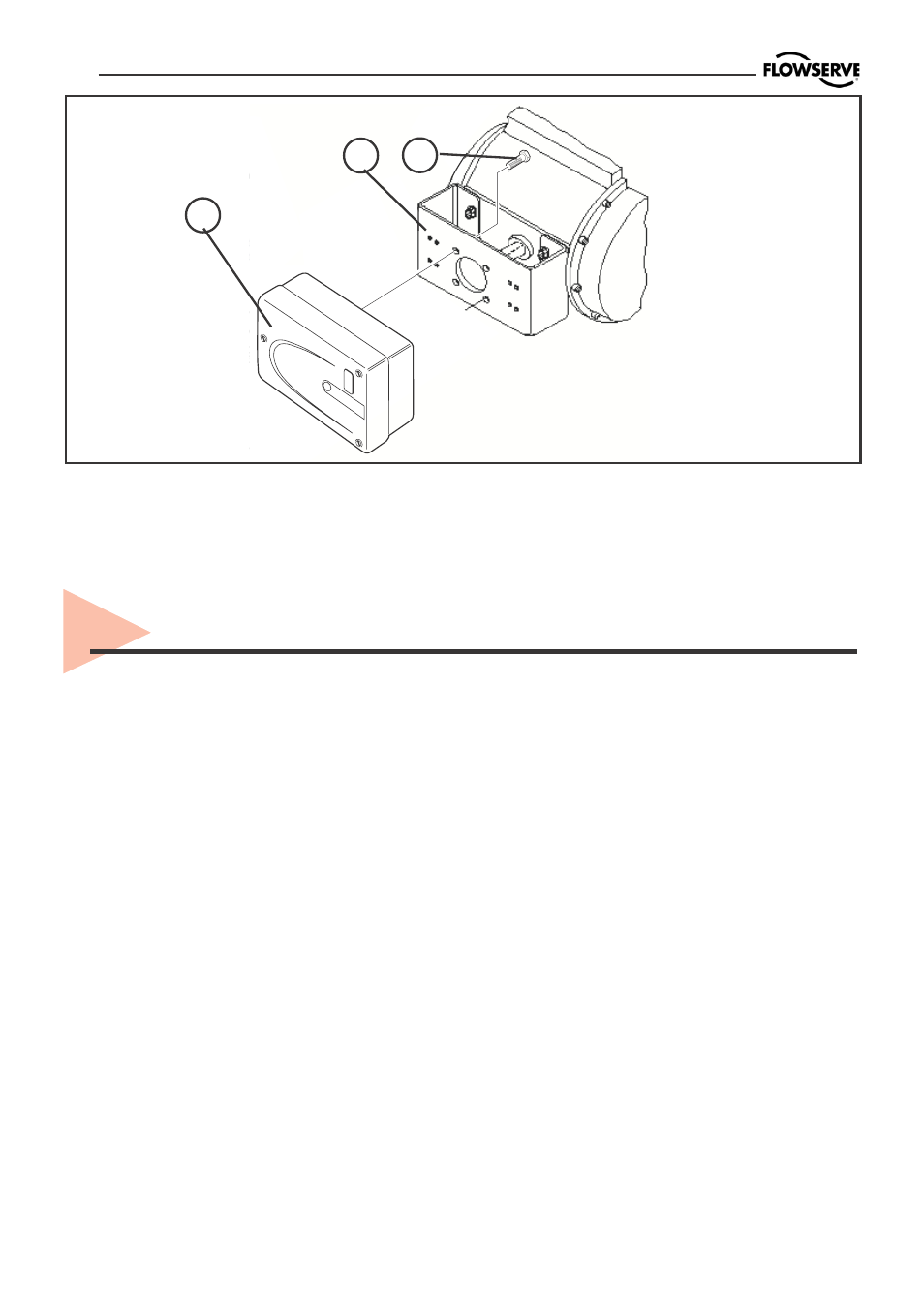
Figure 7. Mounting a Part-turn
Valve Actuator in acc. with VDI/
VDE3845
1
2
3
After mounting has been completed,
tube the positioner to the actuator using
the appropriate compression fitting
connectors:
Air connections: 1/4” NPT (standard air
connection).
Auxiliary power: Pressurized air or
permissible gases, free of moisture and
dust in according with IEC 770 or ISA
7.0.01.
Pressure range: 1,5 – 6 bar (30 – 90 psi).
For connecting the air piping, the
following notes should be observed:
1. The positioner passageways are
equipped with filters, which remove me-
dium and coarse size dirt from the
pressurized air. If necessary, they are
easily accessible for cleaning.
Mounting the positioner (Figure 7)
Place the positioner (1) onto the
mounting block (2) of the actuator using
four screws (3) Ensure the coupler fits
on to the shaft of the quarter-turn
connection on the part-turn valve
actuator.
2. Supply air should meet IEC 770 or ISA
7.0.01 requirements. A coalescing filter
should be installed in front of the supply
air connection (Figure 8). Now connect
the air supply to the filter, which is
connected to the PMV D20 positioner.
3. With a maximum supply pressure of 6
bar (102 psi) a regulator is not required.
4. With an operating pressure of more
than 6 bar (90 psi), a reducing regulator
is required.
The flow capacity of the regulator must
be larger than the air consumption of the
positioner (7 Nm
3
/h @ 6 bar / 4,12 scfm
@ 90 psi).
5. Connect the outlet connector (Figure
8) of the positioner with tubing, indepen-
dent of the action (direct or reverse).
7. Tubing positioner to actuator