Flowserve BTV 2000 Lined Butterfly Valve User Manual
Page 11
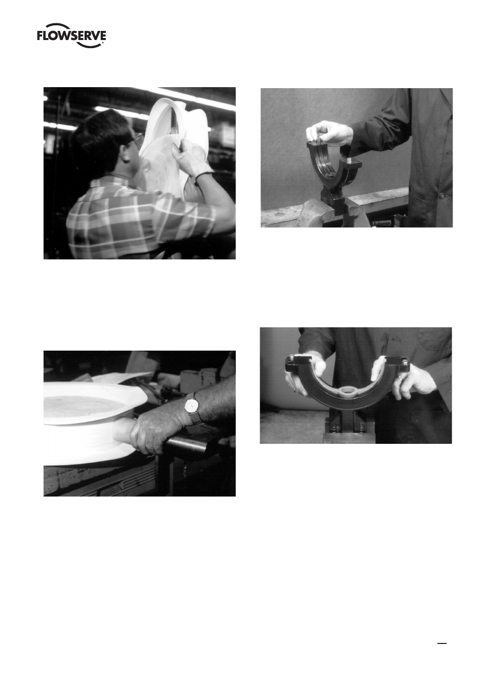
Figure 9
3. All Sizes
Make sure the liner and disc are clean and then close the
disc into the liner to stretch the liner back into shape. Slide
the liner stem seal die (repair tool item 1) and push it up
tightly against the liner (Figure 10). Allow the dies to remain
in place for at least 5 minutes. Note that the end of the liner
stem seal die with the internal chamfer should be towards
the liner when installed.
Figure 10
4. All Sizes
Clamp the bottom body half in a vise and place the body
bushings (1C) into the counterbored holes on diagonal
corners (Figure 11). Either body half can be used as top or
bottom, except for the 2” and 3”. On these sizes, the body
half with the blind stem bore is the bottom.
Figure 11
5.
Sizes 2” - 12”
Place the seat energizer (11) in the bottom body half
(Figure 12). Be sure that the energizer is firmly pushed
into the groove in the body. Also note the orientation of the
angled cuts on the ends of the energizer. When placing the
seat energizer into the top body half, the orientation of the
angled cuts must be opposite to the bottom half.
Figure 12
Sizes 14” - 24”
The seat energizers on these sizes must be trimmed to
length. Place the seat energizer in the bottom body half.
Be sure that the energizer is firmly pushed into the groove
in the body. Mark the seat energizer where it reaches the
machined end of the body half (Figure 13). Remove the seat
energizer and cut each end square at the mark. Place the
seat ener gizer back into the groove being sure it is firmly
pushed into the groove. The cut end of the seat energizer
should be flush to 1/16” above the machined end of the
body half.
11
BTV/BUV 2000
- BUV 2000 Lined Butterfly Valve McCANNA General Purpose Threaded MARPAC General Purpose Threaded Cartridge Seals 582 Mixerpac 2561 Mixerpac 2562 Mixerpac 579 Mixerpac 2563 Mixerpac 2564 Mixerpac 591 Mixerpac 581 Mixerpac 587 Mixerpac ML-200 Mixerpac 2577 Mixerpac 2554 Mixerpac 588 Mixerpac 585 Mixerpac Seal Gard Circpac MD Nordstrom Dynamic Balance Plug Valve and Double DB Plug Valve Serck Audco Super-H Plug Valve Serck Audco Twin Isolation Plug Valve Serck Audco Double Isolation Plug Valve Serck Audco Standard Type Plug Valves 51 Series 52 Series