Flowserve BTV 2000 Lined Butterfly Valve User Manual
Page 15
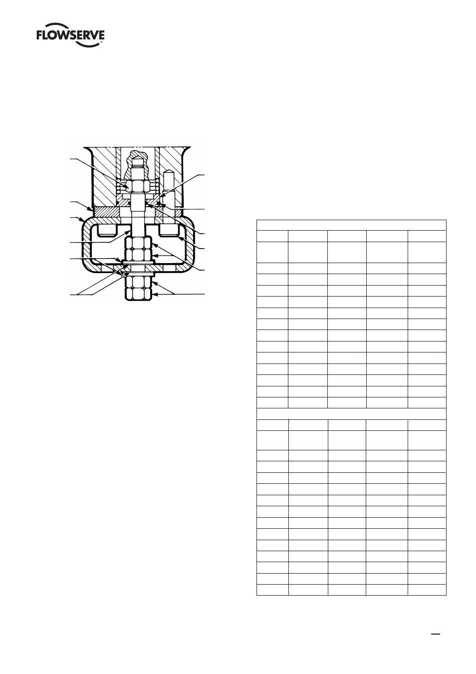
washer (20) on top of the metal washer. It should fit into
the counterbore of the metal washer. Place the disc support
bracket on next with the large center hole facing down,
towards the disc. Install 4 socket head screws and finger
tighten 3 to 4 turns (Figure 23). See note – Table 6.
Figure
23 - 20”
and
24”
Disc
Support
Assembly Detail
14. All Sizes
Align the disc in the closed position so the disc is
centered in the liner. Close alignment is important so use
a scale to ensure the disc is closely centered. Measure at
the 3 o’clock and 9 o’clock positions (Figure 25). These
measurements will be identical with the disc properly
centered. In a criss-cross pattern, tighten the 4 body bolts
and torque to the values listed in Table 4. Be sure to bring
the body halves together evenly. This will require gradual
tightening of each bolt. As the body bolts are tightened,
the disc may rotate out of alignment with the seat. If this
occurs, stop tighten ing immediately, realign the disc in the
seat, and then continue tightening the bolts. Failure to bolt
the body halves evenly will cause them to bind. This may
pre vent the body halves from mating completely using
the specified bolting torques. DO NOT EXCEED TORQUE
SPECIFICATIONS ON BODY BOLTS. See note – Table 6.
15.
Sizes 4” - 12”
Tighten the 4 bottom retainer plate screws in a criss-
cross pattern and torque to the values listed in Table 6.
Be sure to bring the retainer plate down evenly. This will
require gradual tightening of each bolt. Failure to do so will
cause the bolts to bind on the retainer plate and may bend
the retainer plate. When properly in stalled, the retainer
plate will be tight against the body end. DO NOT EXCEED
TORQUE SPECIFICA TIONS ON RETAINER PLATE BOLTS.
See note – Table 6.
Sizes 14” - 18”
Check to make sure that the bottom gland is aligned
with the body stem bore. Tighten the 4 bottom retainer
plate screws in a criss-cross pattern and torque to the
values listed in Table 6. Be sure to bring the retainer plate
down evenly. This will require gradual tightening of each
bolt. Check to make sure that the bottom gland remains
aligned with the body stem bore. If not proper ly aligned,
the gland can bind in the stem bore and may bend the
retainer plate. When properly installed, the retainer plate will
be tight against the body end. DO NOT EXCEED TORQUE
SPECIFICA TIONS ON RETAINER PLATE BOLTS.
See note – Table 6.
TABLE 6 - Bolting Torques
Carbon Steel Fasteners
Part
Body
Body Retainer Retainer
Alloy
B7
(8.8)
4037
(8.8)
Size Ft-Lbs (NM) Ft-Lbs (NM)
2
40
(54)
30
(41)
3
40
(54)
30
(41)
4
40
(54)
30
(41)
5
40
(54)
40
(54)
6
40
(54)
40
(54)
8
80
(108)
40
(54)
10 120 (163) 100
(136)
12 160 (217) 100
(136)
14
180
(244)
100
(136)
16 200 (271) 100
(136)
18 200 (271) 100
(136)
20 250 (339) 100 (136)
24 250 (339) 100 (136)
Stainless Steel Fasteners
Part
Body
Body Retainer Retainer
Alloy B8-40 (A2-70) B8-40 (A2-70)
Size Ft-Lbs (NM) Ft-Lbs (NM)
2
20
(41)
20
(41)
3
20
(41)
20
(41)
4
20
(41)
20
(41)
5
20
(41)
40
(54)
6
20
(41)
40
(54)
8
40
(54)
40
(54)
10
120
(81)
60
(81)
12
160
(81)
60
(81)
14
180
(163)
100
(136)
16 200 (217) 100
(136)
18 200 (217) 100
(136)
20 250 (339) 100 (136)
24 250 (339) 100 (136)
Jam Nut
Retainer
Plate
Disc
Support
Bracket
Disc
Support
Stud
Metal
Washer
PTFE
Thrust Washer
Bottom
Gland
Outer
O-Ring
Inner
O-Ring
Retainer
Plate Bolt
Inner
Jam Nuts
Outer
Jam Nuts
15
BTV/BUV 2000
- BUV 2000 Lined Butterfly Valve McCANNA General Purpose Threaded MARPAC General Purpose Threaded Cartridge Seals 582 Mixerpac 2561 Mixerpac 2562 Mixerpac 579 Mixerpac 2563 Mixerpac 2564 Mixerpac 591 Mixerpac 581 Mixerpac 587 Mixerpac ML-200 Mixerpac 2577 Mixerpac 2554 Mixerpac 588 Mixerpac 585 Mixerpac Seal Gard Circpac MD Nordstrom Dynamic Balance Plug Valve and Double DB Plug Valve Serck Audco Super-H Plug Valve Serck Audco Twin Isolation Plug Valve Serck Audco Double Isolation Plug Valve Serck Audco Standard Type Plug Valves 51 Series 52 Series