Flowserve BTV 2000 Lined Butterfly Valve User Manual
Page 6
1. The protective covers provided on each valve should
remain in place during any storage and handling
operations.
2. The Durco Butterfly Valve is designed for installation
between ANSI Class 150 flanged piping systems. All
types of flanges are permissible if clearance is provided
for the swing of the disc and support is provided for the
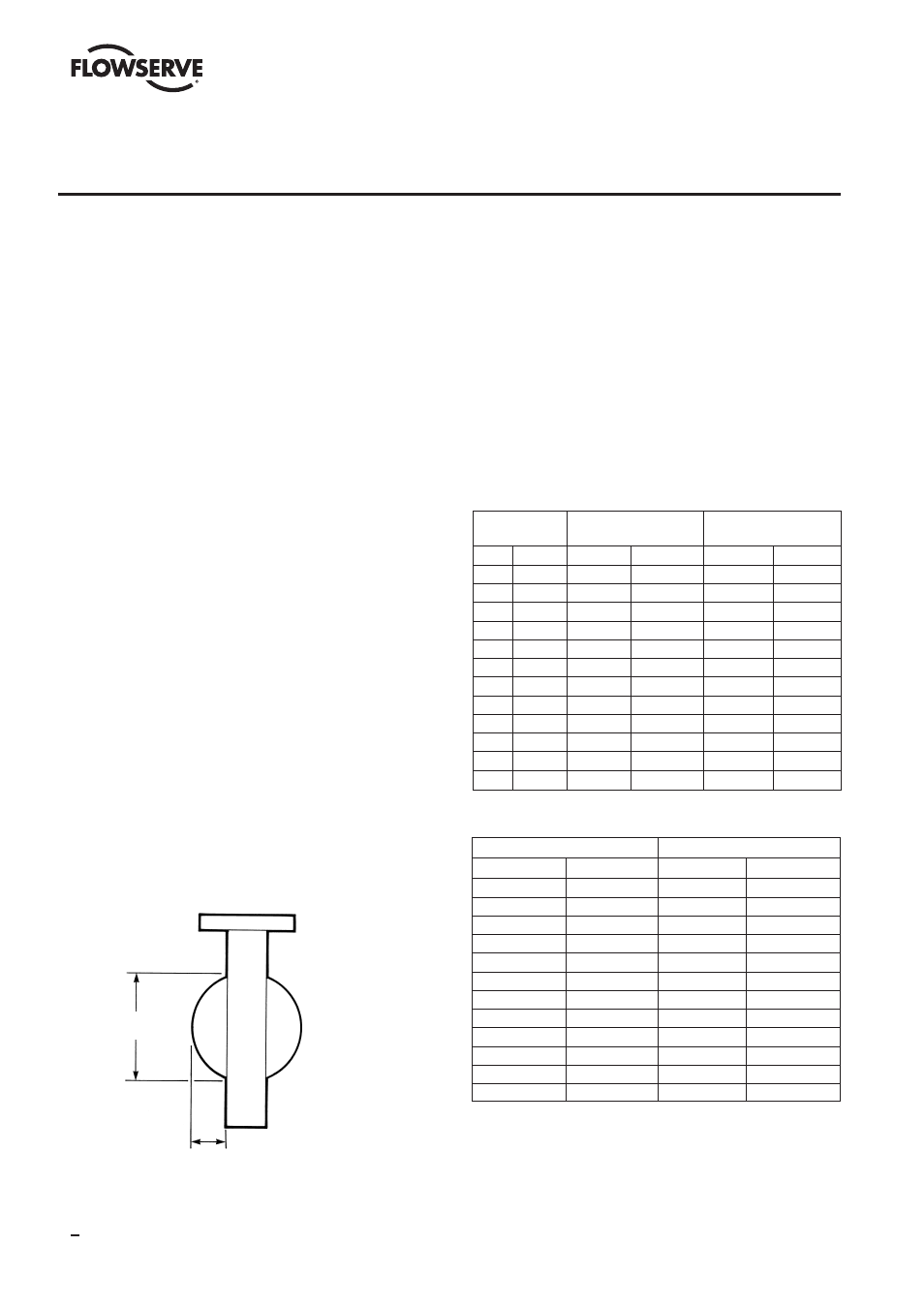
valve liner. Table 3 lists disc swing clearance require-
ments for mating pipe flanges. IMPORTANT – Fittings
such as tees and elbows cannot be bolted directly to the
valve. Spacers must be used.
3. Check the valve nameplate before installation to ensure
that the pressure rating and materials of construction
are compatible with the intended service conditions.
4. Inspect adjoining pipelines and remove any material that
could damage the valve liner.
5. Use flange gaskets to protect the valve liner during
installation.
6. Keep the valve in the closed position during all handling
and installation operations. This is necessary to protect
the disc sealing edge from damage and to ensure proper
positioning of the liner until the valve is installed.
7. Keep the valve liner clean. Any dirt or debris left in the
valve can scratch the liner or disc edge. Such damage
can impair the bubble tight shutoff provided by this
valve.
8. Do not allow the liner to catch on the mating pipe I.D.
and fold over. This will cause flange leakage and severe
damage to the liner.
9. While the BTV valve is bidirectional and will function
properly with the shaft orientation either vertical or
horizontal, the preferred orientation is with the shaft
horizontal and the disc lower edge opening downstream
for optimal service life.
10. Proper alignment of the valve in mating flanges is
required. This is especially true if oversize bolt holes
are used in piping flanges.
11. Flange bolts should be torqued to values listed in Table 4.
12. After
the valve has
been
installed between
flanges and all
flange bolts have
been
tightened, slowly
turn
the disc and
check
for freedom of
disc
movement.
13. If
the valve is to be
removed from the
pipeline for any
reason, the
valve
must be closed
before any of the
flange bolts are
loosened. The valve must remain closed until removed
from the pipeline. SEE SAFETY PRECAUTIONS.
14. For recommended flange bolting sizes and lengths, refer
to Tables in Section XI and XII.
DO NOT run sharp instruments between the valve and liner
or between the liner and the pipe flanges. This practice will
result in severe liner damage.
TABLE 3
TABLE 4
Flange Bolting Torques
These are minimum torque values as established in Section
VIII of the ASME Boiler Code. Your piping practices,
materials and gaskets may dictate the use of torque values
greater than those listed. Refer to Section VIII of the ASME
Code for proper bolting torques.
SECTION II
INSTALLATION
VALVE
DISC
DISC DIM. AT
SIZE
PROJECTION
VALVE FACE
IN (MM)
IN
(MM)
IN
(MM)
2
(51)
0.390
(9.91)
1.805
(45.85)
3
(76)
0.672
(17.06)
2.586
(65.68)
4 (102)
0.994
(25.24)
3.487
(88.56)
6 (152)
1.860
(47.24)
5.510
(139.9)
8 (203)
2.688
(68.27)
7.379
(187.4)
10 (254)
3.626
(92.10)
9.569
(243.0)
12 (305) 4.438 (112.7) 11.564 (293.7)
14 (356) 5.071 (128.8) 12.758 (324.1)
16 (406) 5.626 (142.9) 14.718 (373.8)
18 (457) 6.407 (162.7) 16.719 (424.7)
20 (508) 7.157 (181.8) 18.656 (473.9)
24 (610) 7.781 (197.6) 20.750 (527.2)
VALVE SIZE
TORQUE
in
(mm) Ft.-Lbs. (Nm)
2
(51)
49
(66)
3
(76)
84
(114)
4
(102)
61
(83)
6
(152)
123
(167)
8
(203)
164
(222)
10
(254)
155 (210)
12
(305)
198 (268)
14
(356)
246 (334)
16
(406)
230 (312)
18
(457)
331 (449)
20
(508)
303 (411)
24
(610)
458 (620)
Disc Dimension
at Valve Face
Disc Projection
6
BTV/BUV 2000
- BUV 2000 Lined Butterfly Valve McCANNA General Purpose Threaded MARPAC General Purpose Threaded Cartridge Seals 582 Mixerpac 2561 Mixerpac 2562 Mixerpac 579 Mixerpac 2563 Mixerpac 2564 Mixerpac 591 Mixerpac 581 Mixerpac 587 Mixerpac ML-200 Mixerpac 2577 Mixerpac 2554 Mixerpac 588 Mixerpac 585 Mixerpac Seal Gard Circpac MD Nordstrom Dynamic Balance Plug Valve and Double DB Plug Valve Serck Audco Super-H Plug Valve Serck Audco Twin Isolation Plug Valve Serck Audco Double Isolation Plug Valve Serck Audco Standard Type Plug Valves 51 Series 52 Series