Flowserve BTV 2000 Lined Butterfly Valve User Manual
Page 14
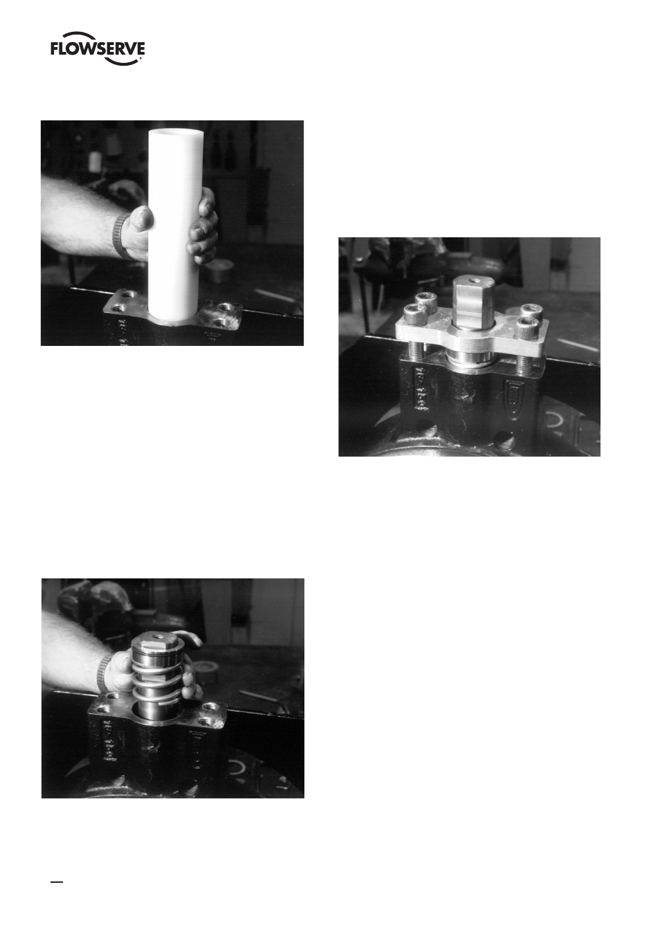
bore. Take the larger diameter o-ring (5B) and put it into
the outside groove of the top gland (5). Place the smaller
diameter o-ring into the inside groove of the gland. Slide
the gland over the disc stem. The outside o-ring must be on
top, away from the disc (Figure 21). Place the ground spring
(22) over the disc stem.
Figure 21
12. All Sizes
Place the retainer plate (3) over the disc stem on top of
the ground spring and gland. Find the two longest socket
head screws (4) and finger tighten them 3 to 4 turns into
diagonally opposite holes as follows: facing the valve body,
put one in the front hole on the left side of the body stem
bore and the other in the back hole on the right side. Put
two short socket screws (4A) in the other two holes and
finger tighten 3 to 4 turns (Figure 22). See note – Table 6.
Figure 22
13.
Sizes 4” - 6”
Turn the valve over and place the stem extension (14)
into the hole in the bottom disc stem. Install the stem
compression ring, stem wedge ring, bearing, shims, spring,
and bottom gland (12) with o-ring per the instructions in
steps 10,11 and 12. Note that the retainer plate screws on
the bottom are all the same length. See note – Table 6.
Sizes 8” - 18”
Turn the valve over and install the stem compres sion
ring, stem wedge ring, bearing, shims, spring, and bottom
gland (12) with o-ring per the instructions in steps 10, 11,
and 12. Note that the retainer plate screws on the bottom
are all the same length. See note – Table 6.
Size 20” and 24”
Turn the valve over and install the stem compres sion
ring, stem wedge ring, bearing, shims and spring per the
instructions in steps 10, 11 and 12. Place the small o-ring
(5B) in the groove on the inside bore and the large o-ring
in the groove on the outside of the bottom gland. Orient the
gland with the outside o-ring on top, away from the disc
and carefully slide the gland over the disc support stud.
Place the retainer plate on top of the gland. Next, thread 2
nuts (18) onto the disc support stud until they are touching
the retainer plate. Slide the metal washer (19) over the disc
support stud such that the recessed counterbore is facing
upwards, away from the disc. Next place the PTFE thrust
14
BTV/BUV 2000
- BUV 2000 Lined Butterfly Valve McCANNA General Purpose Threaded MARPAC General Purpose Threaded Cartridge Seals 582 Mixerpac 2561 Mixerpac 2562 Mixerpac 579 Mixerpac 2563 Mixerpac 2564 Mixerpac 591 Mixerpac 581 Mixerpac 587 Mixerpac ML-200 Mixerpac 2577 Mixerpac 2554 Mixerpac 588 Mixerpac 585 Mixerpac Seal Gard Circpac MD Nordstrom Dynamic Balance Plug Valve and Double DB Plug Valve Serck Audco Super-H Plug Valve Serck Audco Twin Isolation Plug Valve Serck Audco Double Isolation Plug Valve Serck Audco Standard Type Plug Valves 51 Series 52 Series