Flowserve BTV 2000 Lined Butterfly Valve User Manual
Page 16
Important Note: For stainless steel or other high alloy
fasteners with a yield strength below 70,000 psi, it may
be necessary to use B7 fasteners for the initial assem bly.
Once the valve is fully assembled, each fastener must then
be removed one at a time and replaced with the high alloy
fastener. The high alloy fasteners must be torqued to the
levels specified in Table 6.
Size 20” and 24”
Check to make sure that the bottom gland is aligned with
the body stem bore. Tighten the 4 bottom retainer plate
screws in a criss-cross pattern and torque to the values
listed in Table 6. Be sure to bring the retainer plate down
evenly. This will require gradual tightening of each bolt.
Check to make sure that the bottom gland remains aligned
with the body stem bore. If not proper ly aligned, the gland
can bind in the stem bore and may bend the retainer plate.
Also, check to make sure that the jam nuts do not bottom
on the disc support bracket as the retainer screws are
tightened. It may be necessary to thread the nuts further
down on the disc support stud as the retainer screws are
tightened to maintain clearance. When properly installed,
the retainer plate will be tight against the body end. DO NOT
EXCEED TORQUE SPECIFICATIONS ON RETAINER PLATE
BOLTS. See note – Table 6.
After the retainer bolts are tightened, finger tighten the
inner jam nuts against the disc support bracket. Place the
outer PTFE thrust washer, the metal thrust washer with
the shallow counterbore facing down against the PTFE
washer, and 2 outer jam nuts on the disc support stud.
Finger tighten the jam nuts against the disc support bracket.
Using a wrench on the inner and outer jam nuts located
against the inner and outer metal washers, simultaneously
torque the nuts to approximately 40 ft-lbs. This will seat
the PTFE thrust washers against the bearing surface of
the disc support bracket. Then tighten the second jam nut
against the first jam nut to 100 ft-lbs. Make certain that when
tightening the second jam nut, the first jam nut or the disc
support stud does not turn. When complete, tack weld the
jam nuts together (Figure 23).
16. All Sizes
Tighten the 4 top retainer plate screws following the
instructions in step 15. After all four screws are torqued to
the values listed in Table 6, remove the two longest retainer
screws (installed in step 5). Place the mount ing plate (13)
on top of the retainer plate, reinstall the two long retainer
screws (Figure 24) and torque to the values listed in Table
6. See note – Table 6.
17. All Sizes
Carefully clean all exposed liner surfaces. Cycle the valve
5 to 6 times making sure the disc swings com pletely through
the liner in both directions. The initial breaking torque will
be high. Cycling the disc several times helps to “set” the
liner and seat energizer plus smooth out any ridges that may
have formed in the liner during assembly. A small amount of
lubricant, such as silicon, applied to the disc sealing diameter
will help reduce the initial torque. BE CAREFUL to avoid dirt
or grit contamination in the liner as this can scratch the
sealing edge of the disc or liner which will com pro mise the
bubble tight shutoff provided by this valve.
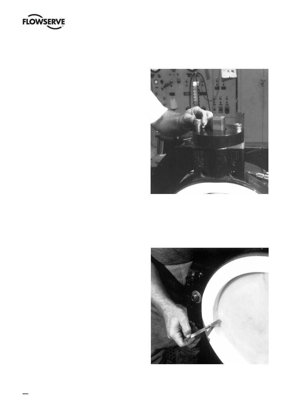
Figure 24
18. All Sizes
Align the disc in the closed position so that the disc is
centered in the liner. Close alignment is important so use
a scale to ensure the disc is closely centered. Measure at 3
o’clock and 9 o’clock positions. These measurements will
be identical with the disc properly centered (Figure 25). The
valve is now ready for the actuator to be installed.
Figure 25
16
BTV/BUV 2000
- BUV 2000 Lined Butterfly Valve McCANNA General Purpose Threaded MARPAC General Purpose Threaded Cartridge Seals 582 Mixerpac 2561 Mixerpac 2562 Mixerpac 579 Mixerpac 2563 Mixerpac 2564 Mixerpac 591 Mixerpac 581 Mixerpac 587 Mixerpac ML-200 Mixerpac 2577 Mixerpac 2554 Mixerpac 588 Mixerpac 585 Mixerpac Seal Gard Circpac MD Nordstrom Dynamic Balance Plug Valve and Double DB Plug Valve Serck Audco Super-H Plug Valve Serck Audco Twin Isolation Plug Valve Serck Audco Double Isolation Plug Valve Serck Audco Standard Type Plug Valves 51 Series 52 Series