Wiring diagram lrr 1- 40, Wiring, Fig. 4 fig. 5 – Flowserve LRR1-40 TDS Control Unit User Manual
Page 16
Advertising
16
– con tinued –
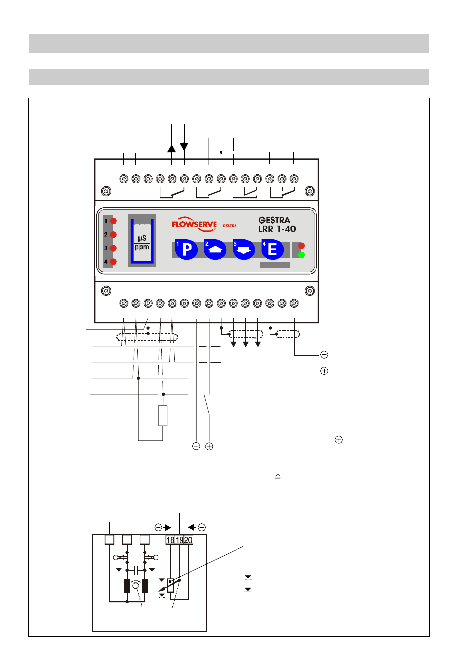
Wiring diagram LRR 1- 40
1
2
3
27
16
L
N
N
1
L
H
1
+
-
C
C
S
2
3
4
5
6
7
8
17 18 19 20 21 22 23 24
9
25
10
26
11 12
28
13
29
14
30
15
23
25
Potentiometer
24V AC /DC
Observe polarity
with DC!
MAX limit
Safety circuit
24 V DC
CAN bus
Actual value output
4-20mA (option)
Terminating resistor
120
Ω
5V DC
L
L
L
C L OS ED
L
OPE N
MIN limit
N
L
N 25 23
12
10
11
Continuous blowdown control
= Valve OPEN 25
= Valve CLOSED 23
Actuator
Continuous blowdown valve BAE 36 -1
Feedback potentiometer 1000
Ω
Fig. 4
Fig. 5
Test
Contact in burner control,
if stand-by function is desired.
Terminal 7/8
Voltage input 24V
AC /DC for external command
contact closed
Control OFF, valve CLOSED,
intermittent blowdown OFF [Stand-by]
(Might come from bus supply.)
S
Twisted pair
cables
Advertising