Max limit / min limit, Operation – Flowserve LRR1-40 TDS Control Unit User Manual
Page 24
24
– co ntinu ed –
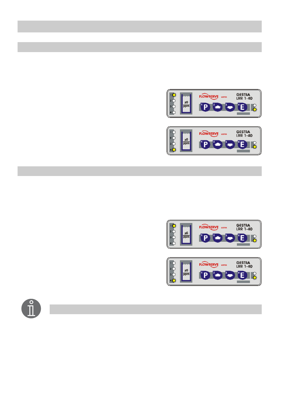
MAX limit / MIN limit
Only applicable if:
■
Relay contact 1 (feedback LED 1) works as switching output for MAX limit
■
Relay contact 4 (feedback LED 4) works as switching output for MIN limit
LED 1 lights up once the set MAX limit is reached.
Relay contact 1 opens (safety circuit).
LED 1 goes out once the value falls below its limit.
Relay contact 1 closed.
LED 4 lights up once the set MIN limit is reached.
Relay contact 4 opens.
LED 4 goes out once the value exceeds its limit.
Relay contact 4 closed.
MAX limit / MIN limit = Automatic intermittent boiler blow down
Only applicable if:
■
Relay contact 1 (feedback LED 1) works as switching output for MAX limit and MIN limit
■
Relay contact 4 (feedback LED 4) works as switching output for automatic intermittent
boiler blowdown
LED 1 lights up once the set MAX or MIN limit is
reached. Relay contact 1 opens (safety circuit).
LED 1 is not lit if the actual value is between the MIN
and MAX limit. Relay contact 1 closed.
LED 4 is lit during intermittent blowdown and relay
contact 4 is closed. The intermittent blowdown valve
opens.
LED 4 is not illuminated during the time between
intermittent blowdown. Relay contact 4 is open, the intermittent blowdown valve is closed.
Test
Test
Test
Test
Note
The MIN limit is activated approx. 60 seconds after the mains voltage has
been applied. During this time LED 1 or - depending on the setting - LED 4
is flashing rapidly.