Flowserve NAF-Turnex pneumatic actuators User Manual
Page 10
10
3.2 To dismantle and assemble the spring-
return unit
If the air consumption of the spring cylinder in size 0 and
1-3 actuators is abnormally high, it may be necessary to
dismantle the spring-return unit to replace the sealing
ring.
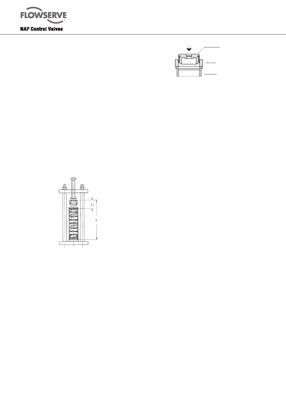
The equipment shown in Fig. 12 is necessary for
unloading or preloading the springs to enable the spring-
return unit to be dismantled and assembled. Table 3
shows the compression force, free height and preloading
travel necessary. In addition, the tool shown in Fig. 13 is
necessary for fitting the piston into the spring-return unit
in size 1-3 actuators.
Spring-
Compression
Free
Preloading
return
force
height
travel
unit
N
L, mm
Lf, mm
0
750
250
85
1
1200
350
110
2
3100
505
185
3
7900
645
195
Table 3. Assembly particulars for each size of spring-return unit
Fig. 12. Spring unloading tool
The spring-return unit in sizes 4-5 actuators need not normally
be dismantled. However, if this should be necessary for any
reason, we would advise you to consult NAF.
3.3 To dismantle the spring-return unit
Sizes 0 and 1-3, see Fig. 10, 19.0 and 19.1
1. Remove the end stops (7, 8, 9) on both sides of the
actuator.
This must be done to ensure that the preloading
which may remain in the spring will not project the
spring cylinder and thus cause damage or injury.
Fig. 13. Assembly
2. Release the nuts (6) in diagonally opposite pairs at
the spring cylinder. However, leave all nuts in position
until all spring load has been relieved. Then remove
the nuts and the end cover (59).
3. Back off the long piston nut about two turns. Place
a sturdy metal drift against the long piston rod nut,
and hammer the drift until the piston rod is released
from the piston in the cylinder. Unscrew the piston rod
nut. The spring cylinder can now be removed.
Make sure that the spring cylinder does not
point towards any person, since it contains
preloaded springs.
4. Secure the spring-return unit in the spring unloading
tool (Fig. 12). The spring guide (57) should be in
contact with the push-rod of the tool. If necessary,
place a protective plate under the push-rod.
It is essential to secure the spring-return unit in the
tool so that it is perfectly vertical and so that it
will not become misaligned due to possible
transverse forces from the spring.
5. Press the spring guide (57) and springs (55) into the
cylinder (53), so that the entire locking ring (58) is
exposed.
6. Carefully remove the locking ring (58) without
damaging it.
7. Unload the spring completely. Remove the spring
guide (57) and the springs (55). Take care
not to damage the cylinder bore.
8. Remove the cylinder from the tool and carefully
remove the remaining locking ring (58). Then push the
piston out from this side.
9. Clean the various parts and inspect them from wear.
The part of the cylinder bore which is in contact with
the piston must be free from scratches, although
minor scratches are permissible on the part of
the cylinder bore around the spring.
Size 4
1. If possible, place a spring-return actuator with the
spring cylinder pointing upwards. Back off the nut
sleeves (50) (see Fig. 19.4) gradually one turn at
a time until all studs have been entirely relieved
of load.
2. Withdraw the cylinder straight up.
3. Remove the spring assembly.
N.B. Do not dismantle the spring assembly.
Special equipment is necessay for this purpose.