Flowserve NAF-Turnex pneumatic actuators User Manual
Page 3
3
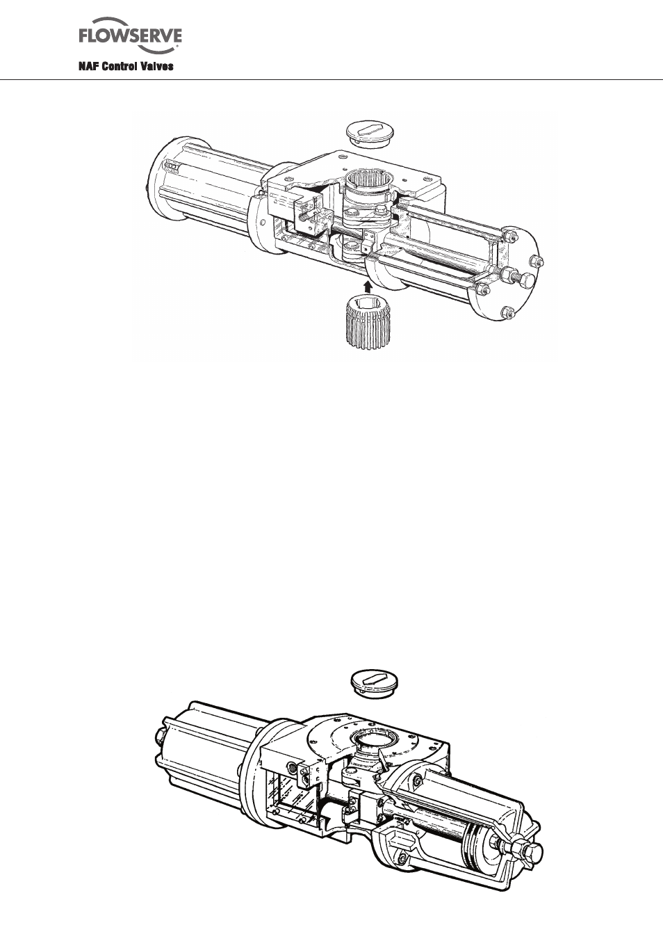
Fig. 2.1. NAF-Turnex, sizes 1 - 3
Sizes 4-5 (Fig. 19.4)
1. Remove the air cylinder retaining bolts (12) and
carefully remove the cylinder.
2. Withdraw the cylinder straight up.
3. Remove the locking screws (45) and remove the cover
(2).
4. Release the locking links (8) as shown in Fig. 1.4 and
Fig. 19.4 by prising apart the locking clip (10A) by
means fo circlip pliers, and withdraw the pins (9A) by
means of a screw (M5/M8) screwed into them.
5. Turn the links so that the lever lugs are exposed and
lift out the lever.
6. If the actuator has two pistons (32), fit a ring spanner
to each of the piston nuts (36) and then turn the
spanners anti-clockwise until one of the nuts is
released. Remove the nut and the piston.
N.B. Never use the piston or piston rod as restraint
for releasing the other piston unit. Take a slit nut instead
(with a slit width of 2-3 mm), and screw it onto the free
end of the piston rod. Grip the slit nut with the pipe
wrench and restrain it while releasing the other piston nut.
Take care not to scratch the piston rod. Scratches
could cause damage to the piston rod seal.
7. If the actuator has only one piston, remove the piston
nut by means of a slit nut as described above.
8. Remove the screws (14) from the coupling (25).
9. Pull away the coupling (25) and use circlip pliers
to open up the circlip (26). At the same time, carefully
withdraw the piston rod (31) from the seal holders
(42), couplings (25 and 27) and circlip (26).
Inspect for damage and wear in accordance with section
2.2. Re-assemble the actuator as described in section 2.6.