Flowserve NAF-Turnex pneumatic actuators User Manual
Page 7
7
Sizes 1-3
1. Make sure that all parts have been thoroughly cleaned.
Wipe clean the cylinders (1, 16), bearing surfaces of
the lever (21), and other sliding surfaces.
2. If the linkage mechanism (Fig. 1) has been
dismantled, re-assemble it. Fit the links (12-14) to the
coupling pins (31). Then fit the circlips (11) and
assemble the links with the lever (21) and pins (23).
Finally, fit the circlips (22).
3. Grease the bearings (38) and O-rings (37). Fit them
into the housing (30) and cover (29), and to the
lever (21). Fit the linkage mechanism into the housing.
Make sure that the lever is fitted with the milled driver
grooves facing upwards (towards the cover 29),
and that the mounting plate (33) on the coupling faces
outwards towards the window (35).
4. Rub a thin film of grease onto the surface ot the piston
rod (26). Carefully push the piston rod past the piston
rod seal (27), through the bearing (28), coupling (31)
and out through the opposite bearing and seal.
N.B. The location of the hole in the piston rod is not
symmetrical. The side of the piston rod which is
longer (from the hole to the end) should be located on
side A as shown in Fig. 19.1.
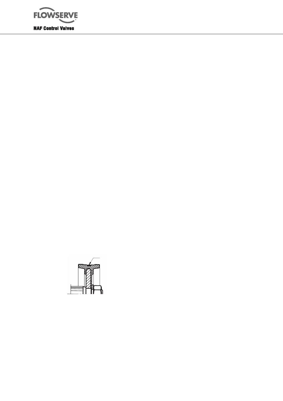
5. Coat the lips of the pistons (25) with a thin film of
grease, and make sure that the groove between the
lips is filled with grease. See Fig. 9. Fit the pistons to
the piston rod (26), with the rubber-coated side facing
the nut. Apply locking compound to the piston rod
thread. Fit the washer (24.1) and nut (24). After the
pistons have been fitted, tighten the nuts
simultaneously to the torque specified in Table 1.
6. Align the hole in the piston rod (26) with the hole in
the coupling (31). Apply some anti-galling agent, such
as Molycote, to the unthreaded part of the pin (10),
and then fit the pin into the coupling.
The pin should enter easily into the hole. Never
use force. It may sometimes be necessary to rotate
the piston rod through half a turn. Tighten the pin to
the torque specified in Table 1.
7. Fit all the tie rods (2).
8. Grease the O-rings (3, 17), and fit two of the O-rings
(3) and both O-rings (17).
Fig. 9. Lubrication of the piston
Grease
9. Apply a thin film of grease to the surfaces of the
cylinders (1, 16) and use a clean piece of lint-free
linen cloth to work the grease into the whole of the
sliding surface. Carefully push the cylinders onto the
pistons.
One actuator size 1, the cylinders on sides A and B
are different.
10. Fit the O-rings into the end covers (4) and fit the
covers to the cylinders. Then fit the washer (5) and
nuts (6) to the tie rods and tighten the nuts in
diagonally opposite pairs to the torque specified in
Table 1.
11. Fit the cover (29). Apply a little locking compound to
the threads of the screws (18), and tighten the screws
to the torque specified in Table 1.
12. Adjust the end-stop bolts (9) to the required end
positions.
Sizes 4-5
1. Make sure that all parts have been thoroughly cleaned.
Wipe clean the cylinders (35), bearing surfaces of the
lever (6), and other sliding surfaces.
2. If the linkage mechanism (Fig. 1) has been
dismantled, re-assemble it. Fit the links (8A) to the
coupling pins (25). Then fit the circlips (19) and
assemble the links with the lever (6) and pins (9A).
Finally, fit the locking clips (10A).
3. Grease the bearings (3, 4, 15 and 16) and O-rings (7,
17). Fit them into the housing (1) and cover (2), and
to the lever (6). Fit the linkage mechanism into the
housing. Make sure that the lever is fitted with the
milled driver grooves facing upwards
(towards the cover 2).
4. Rub a thin film of grease onto the piston rod (26).
Carefully push the piston rod past the piston rod seal
(42), through the bearing (11), the coupling (25 and
27 and the opened-up locking clip 26) and out
through the opposite bearing and seal.
5. Coat the faced O-ring (34) on the pistons (32) with a
thin film of grease. Fit the piston to the piston rod
(26) with the chamfered recess side towards
the nut. Apply some locking compound to the piston
rod thread. Fit the nut (36). After the pistons have
been fitted, tighten the nuts simultaneously to
the torque specified in Table 2.
6. Guide the circlip into the piston rod groove and lock it.
Tighten the two halves of the coupling (25) and (27),
using the screws (14).
Table 2. Tightening torques, Nm, for the bolts and nuts of the actuator.
Part
Actuator size
4
5
Piston rod nut (36)
400 800
Bolt (12)
50
80
Locking screw (45)
20
40
Stud (49)
50
80