Flowserve NAF-Turnex pneumatic actuators User Manual
Page 5
5
Remove the circlips (11 and 22, or 19 and locking clip
10A). The figures refer to sizes 0-3 and 4-5 respectively.
The pins and links can now be removed.
Now check the following parts:
Pins (23 and 9A). If these are damaged or heavily
scratched, fit new pins. Minor scratches can be removed
by rubbing down with very fine emery cloth.
Links (12-14 and 8A). The link includes one or two
bushes (14 or 18 respectively) of Glacier manufacture.
This does not apply to size 3 actuator, in which the
bushes are fitted into the link. If the internal PTFE coating
is damaged so that the metal to which it has been applied
is visible through the coating, fit new bushes. See section
2.5.
Lever (21 and 6). The lever includes two bushes (21.1
or 11 respectively) of Glacier manufacture. This does not
apply to size 3 actuator, in which the bushes are fitted into
the link. If the internal PTFE coating is damaged so that
the metal to which it has been applied is visible through
the coating, fit new bushes. See section 2.5.
The coupling (31 or 25 and 27).Check the pins of the
coupling. If these are damaged or heavily scratched, a
new coupling must be fitted. Minor scratches can be
removed by rubbing down with very fine emery cloth.
2.3 To change the piston rod bearings
Size 0
To remove the piston rod bearing (28), insert a small
screwdriver between the bearing and the outside of the
housing (30) and prise away the bearing (see Fig.3).
Press in a new bearing. This is best done in a vice and
should be done quickly so that the bearing will not deform
plastically. After fitting, the bearing should be free to
rotate in the housing, but should be locked in the axial
direction.
Fig. 3. Removing the piston rod bearing
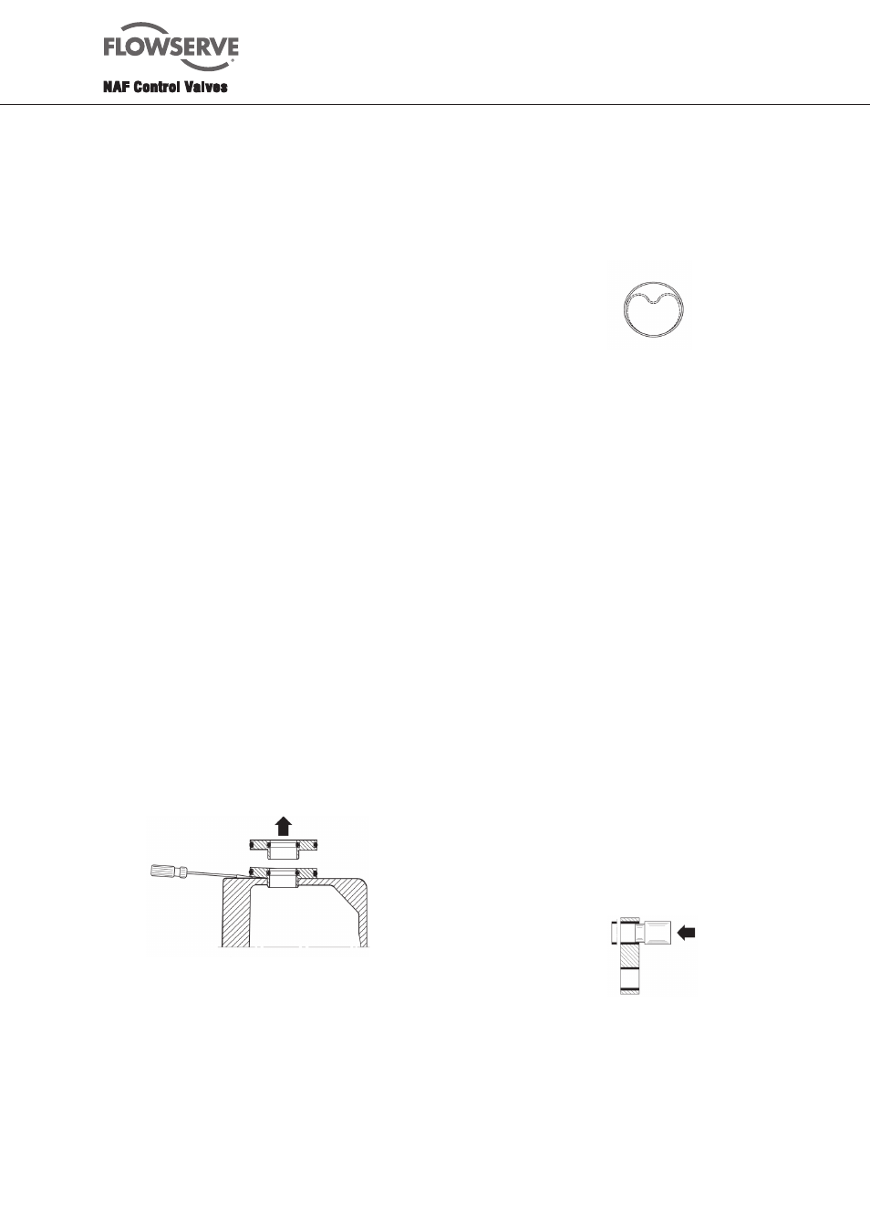
2.4 To change the piston rod seal
Size 1-3 and 4-5
The actuator must be dismantled as described in section
2.1.
1. On sizes 1-3, remove the old piston rod seal (27 or
42) by means of a small screwdriver, for instance.
If the piston rod bearing is to be replaced, this must
be done as described in section 2.5 before continuing.
2. Clean the groove with white spirit and wipe it clean.
3. Fit the O-ring of the piston rod seal or, on sizes 4-5, fit
a complete seal holder (42).
4. On sizes
1-3, place the PTFE ring (27) of the O-ring
piston rod seal in water at 60
°C for 3-4 minutes, so that
it will soften.
5. Grip the ring with your fingers and form it into the
shape shown in Fig. 4.
6. Fit the PTFE ring into the groove and press it back into
its circular shape.
7. Check that the piston rod (26 or 31) is free from
scratches or burrs. If not, use very fine emery cloth to
remove them before fitting the pison rod. Clean the
piston rod with white spirit and then wipe it with a
piece of lint-free linen cloth.
8. On
sizes 1-3, push the piston rod into the seals and
leave it there for at least 10 minutes. The PTFE ring
will then have resumed its original shape and the
piston rod can be removed.
9. On sizes 4-5, fit a complete new seal holder (42).
Apply locking compound to the screws and tighten
them.
2.5 To change the PTFE-coated bushes
Size 0
A drift is needed for changing only the bushes (14) in the
links (12). Make a drift as shown in Fig.5. Use the drift
and a mallet to remove the worn bushes. Use the same
drift to fit the new bushes, using a vice for the purpose.
However, we recommend that the entire link should be
replaced by a new one.
Fig. 4. Forming the PTFE ring for the piston rod
Fig. 5. Changing the bushes in a link
Sizes 1-3 and 4-5
The piston rod bearings (28 or 44), lever bush (21.1 or
18) and link bush (14 or 11) may have to be changed
after a long period of service under difficult conditions.
Replacement must be carried out when the PTFE coating
has become worn so that the metal to which it has been
applied is visible through the coating.