Accessories – Flowserve NAF-Turnex pneumatic actuators User Manual
Page 11
11
The spring assembly consists of springs, spring guide
and guide rails which together form a preloaded spring
assembly. If the assembly must be dismantled for any
reason, get in touch with NAF.
4. Inspect the piston and its guide and faced O-rings as
described in section 2.2.
Size 5
Consult NAF if the spring return unit must be dismantled.
3.4 To assemble the spring-return unit
1. Clean all parts and grease the cylinder bore (see
section 2.5 for particulars of the recommended
grease), using a piece of lint-free linen cloth.
2. Fit a new spring piston assembly (50, 51, 52). For
sizes 1-3, the special tool shown in Fig. 13 which
serves as a ”shoe horn” is necessary for assembly.
The following instructions in section 3.4 are applicable
only to actuators of
Sizes 0 and 1-3
The best results will be achieved by replacing the
entire spring piston. If only the faced O-ring (5) is
replaced, first carefully remove the old ring and then
thoroughly clean the groove. Then place the sliding
part of the ring in water at 60
°C for 3-4 minutes. During
this time, fit the O-ring into the groove. Then firmly grip
the sliding part of the ring, and quickly prise it over the
guiding edge of the piston. Bear in mind that it the ring is
stretched too far, it may remain permanently deformed.
3. Fit the locking ring (58) into the groove in the cylinder,
and then push the spring piston against it so that the
locking ring will be locked by the piston (see Fig. 13).
Fig. 14. Position of locking ring
4. Insert the springs (55) into the cylinder so that the
their ends fit into the grooves on the inside of
the spring piston. Take care not to damage the
cylinder bore.
5. Place the unit in the spring unloading tool shown in
Fig. 12.
It is essential to secure the spring-return unit in the
spring unloading tool so that it is perfectly vertical,
to prevent it from becoming misaligned due to
possible transverse forces from the spring.
6. Place the spring guide (57) on the ends of the springs.
If necessary, place a protective plate under the push-
rod, and then press down the spring guide so that the
entire locking groove is exposed.
7. Fit the locking ring (58) into the locking groove in the
cylinder and then reduce the load very gradually
until the locking ring has gripped the spring guide
(see Fig. 14). Make sure that the spring guide is not
misaligned in the cylinder.
8. Release the spring unloading tool entirely and remove
the unit from the tool.
9. Then fit the spring-return unit to the actuator as
described in section 3.1, items 9-13.
10. Check that the warning plate (62) is fitted to the
cylinder and is fully readable. If necessary, fit a new
warning plate.
Size 4
1. Fit the spring assembly.
2. Push the cylinder into place.
3. Screws on the studs (49) with the nut sleeves (50),
and tighten them alternately one turn at a time. Finally
tightening them to the torque specified in Table 3.
Size 5
See section 3.1, items 5-19.
4. Accessories
Size 0 and 4-5 actuators have a lever arm (21 and 6
respectively) with a keyway in the hub. Sizes 1-3 have
stem sleeves as shown below.
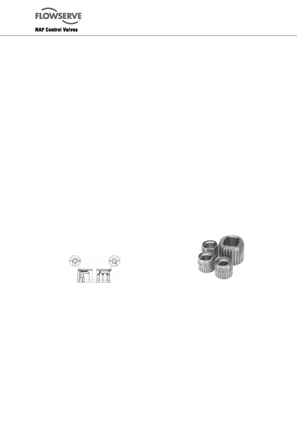
4.1 Stem sleeves
Sizes 1-3
Separate stem sleeve with hole and keyway machined in
accordance with DIN6885 (SS 2304). See Fig. 15. Sleeves
with 16 mm or 25 mm holes without keyway are also
available for each actuators size. See Table 4.
Fig. 15. Stem sleeves for sizes 1 - 3.
Always fit the sleeve from the underside of the actuator,
with the centrepunch mark on the sleeve in line with the
centrepunch mark on the lever side. However, if the actua-
tor is installed in line with the pipe, the sleeve should be
turned through 90
°, although this is unnecessary for sizes
791290/92/94-2 which have 4 keyways. To remove, tap the
sleeve out of the actuator in the opposite direction.
4.2 End position indication
Size 1-3 actuators can be equipped with side-mounted
electrical end-position indicators of the type shown in
Fig. 16. Two types of sensors are available, i.e. magnetic
sensors of reed element type, and inductive sensors. Any
inductive sensor with M18 thread and a sensing distance
of at least 5 mm can be employed. Depending on the type
of sensor, different sensing elements can be used.