Flowserve NAF-Turnex pneumatic actuators User Manual
Page 6
6
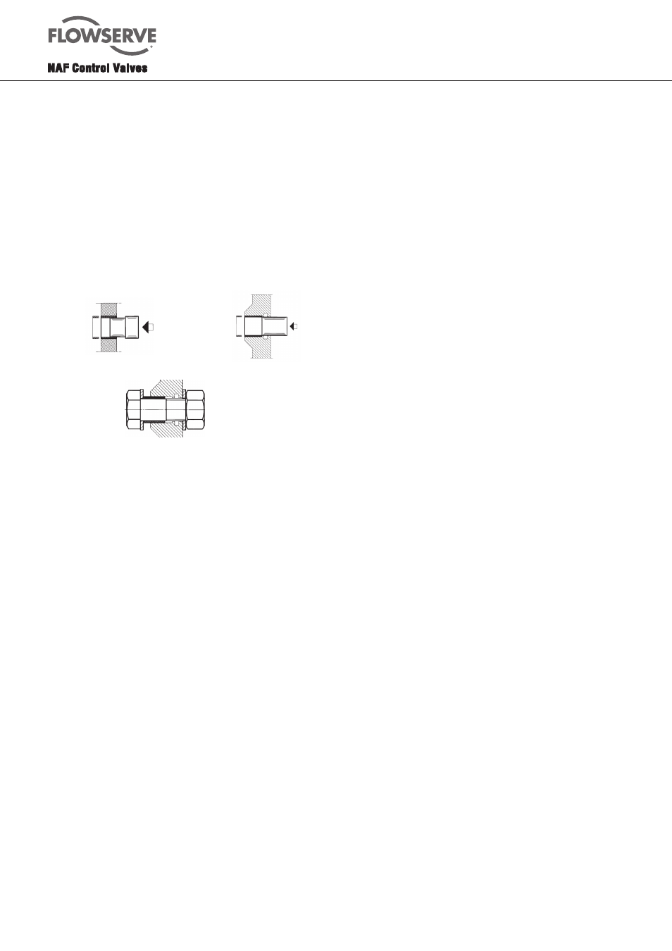
1. To remove the bush. The easiest procedure is to
make a drift as shown in Fig.6 for link and lever bushes,
and a drift as shown in Fig.7 for the piston rod bearing.
The bush can then easily be removed by means of this
drift and a mallet.
2. To fit new bushes. To fit the new bushes (21.1 or 18)
into the lever and new bushes (14 or 11) into the links,
use the same drift as that used for removing them. Use
the drift and a vice, for instance, to press in the bush. The
easiest way of fitting the piston rod bush (28 or 44) is to
press it in by means of a bolt as shown in Fig.8.
Fig. 8. Fitting the piston rod bush
Fig. 6. Drift for the bushes
Fig. 7. Drift for the
piston rod bearing
2.6 Assembly
Grease part No. 349 06 260, which has been tested
by NAF and a leading lubricant manufacturer, is
recommended for all surfaces that require greasing. This
grease has proved to have by far the best properties for
lubricating the contact surfaces between rubber/plastic
and metal. These properties include high load-bearing
capacity, good adhesion, and very low stick-slip effect.
Size 0
1. Make sure that all parts have been thoroughly cleaned.
Wipe clean the cylinders (1, 16), bearing surfaces of
the lever (21), and other sliding surfaces.
2. If the linkage mechanism (Fig.1) has been dismantled,
re-assemble it. Fit the links (12, including the bushes
14) to the lever (21) using the pins (23) and circlips
(22).
3. Grease the O-rings (37) and fit them onto the lever
(21).
4. Grease the O-rings (27) and fit them into the piston
rod bearings (28).
5. Rub a thin layer of grease onto the piston rod (26).
Carefully push the piston rod into the bearing
(28), past the O-ring (27) and out through the
corresponding bearing on the other side of the
housing.
N.B. The location of the hole in the piston rod is not sym-
metrical. The side of the piston rod which is longer (from
the hole to the end) should be located on side A as shown
in Fig. 19.0.
6. Coat the lips of the piston (25) with a thin film of
grease, and make sure that the groove between the
lips is filled with grease as shown in Fig. 9. Fit the
pistons to the piston rod (26) with the rubbercoated
side facing the nut. Apply locking compound to the
piston rod thread. Fit the washer (24.1) and nut
(24). When the pistons have been fitted, tighten the
nuts simultaneously to the torque specified in
Table 1.
7. Place the linkage mechanism (Fig.1) as shown in
Fig.19.0. Fit one of the circlips (11) to the pin (10).
Then push the pin in through the links (12) and piston
rod (26), and lock the pin with the other circlip (11).
8. Fit the lever bearings (38) into the cover (29) and base
(74). The easiest procedure for fitting the bearings is
by using a press or a vice.
9. Apply a little medium-strength locking compound into
the tapped holes, and use the screws (18) to secure
the cover (29) and base (74). See Table 1.
N.B. Fit the cover and base as shown in Fig. 19.0, so that
the linkage mechanism will open in the right direction.
10. Grease the O-rings (3, 17) and fit them into the piston
rod bearings (28) and housing (30) respectively. Two
of the O-rings (3) will be left over and can then be
used in the end cover (4).
11. Apply a thin coat of grease to the surfaces of the
cylinders (1, 16). Work the grease into the whole of
the sliding surface by means of a clean piece of lint-
free linen cloth. Carefully push the cylinders onto the
pistons.
12. Fit the remaining two O-rings (3) into the end covers
(4) and place the covers on teh cylinders. Apply a little
medium-strength locking compound into the M6
tapped holes at the cylinders. Fit the washers (5) and
bolts (2). Tighten the bolts in diagonally opposite pairs
(see Table 1). The tightening torque corresponds
to tightening the bolts by hand until they come into
contact with the end cover, and then tightening about
a further quarter of a turn.
N.B. It is important not to overtighten the bolts since the
tapped holes in the housing may otherwise be damaged.
13. Adjust the end-stop bolt (9) to the required end
position.
Table 1. Tightening torques, Nm, for the bolts and nuts of the actuator
Part
Actuator size
0
1
2
3
Piston rod nut (24, 56)
14 29 50 115
Pin (10)
7 50 115
Tie-rod nut (6)
7 35 35
Locking screw (18)
17
7 17 17
End-cover bolt (2)
7