Assembly, Mounting adjustable legs – Formax FD 4040 User Manual
Page 4
ASSEMBLY
1.
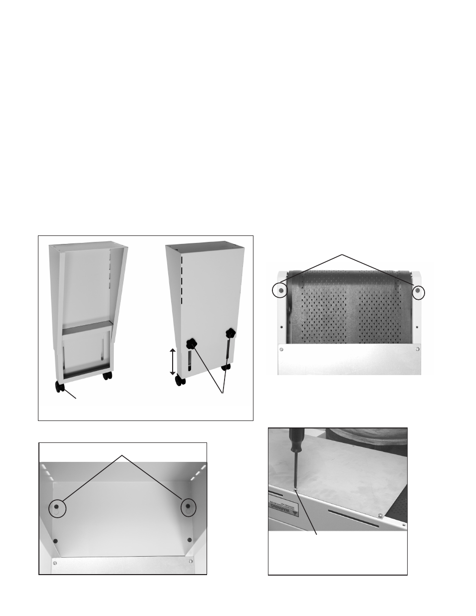
Install 2 swivel casters on each of the leg assemblies (Fig 1 item A). Secure casters with hex nuts.
2.
To pre-adjust leg assemblies to proper length, measure the distance from the floor, to the exit surface of the delivery
device (i.e. printer). Loosen the black hand wheels (Fig 1 item B) and adjust leg assembly until overall length,
including casters, is about 7 inches less than the measurement you just obtained. Tighten hand wheels and repeat
procedure for other leg assembly.
3.
With conveyor laying upside down, install leg assembly. Install two Allen screws to the outer edge of the conveyor
(Fig 2 item C) do not tighten all the way, leave enough space to slide the keyhole, in the top of the leg assembly,
into position (Fig 3 item D). Insert two screws into the two remaining holes, tighten when all screws are in position
(Fig 4). Allen screws are provided in accessory bag.
Assembly Tip (Fig 4): If you have trouble aligning the screw holes in the leg assemblies with the conveyor holes;
loosen the 10 Phillips head screws that secure the bottom plate (Fig 4), to allow the conveyor side frames to flex.
When finished securing leg assemblies to conveyor, be sure to re-tighten these 10 Phillips head screws.
4.
With the legs securely fastened, carefully turn conveyor upright.
Note: If conveyor operation direction needs to be
changed, do so before turning upright - see Control Panel Module Optional Adjustment Pg 3.
CAUTION! Two (2) people are required for lifting and turning conveyor.
To help align holes, when attaching leg
assemblies, loosen screws that secure
bottom plate.
A
B
D
C
Mounting Adjustable Legs
Fig 1
Fig 2
Fig 3
Fig 4
2