Acu description – FSR ML-116 User Manual
Page 13
FSR
ML-116 INSTALLATION DATA
Telephone 973-785-4347
page 13
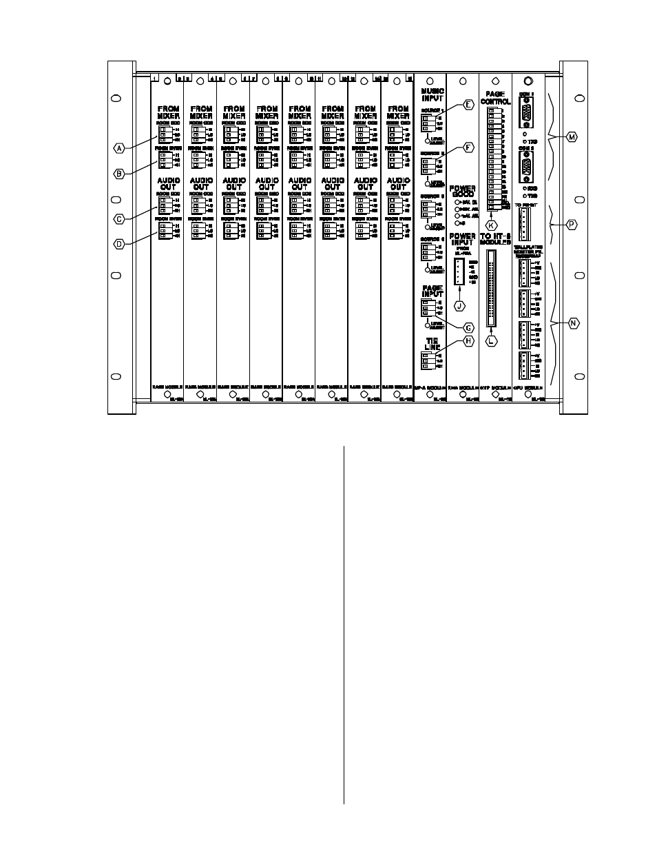
ACU Description
A...This 3 pin connector receives the audio signal
from the ODD room's mixer.
B...This 3 pin connector receives the audio signal
from the EVEN room's mixer.
C...This 3 pin connector provides the audio out-
put to the ODD room's amplfier or EQ.
D...This 3 pin connector provides the audio out-
put to the EVEN room's amplfier or EQ.
E...These four 3 pin connectors receive the back-
ground music signals from the facility supplied
sources. The source number over each connector
corresponds to the identification called out on the
room wallplates.
F...This trim control provides limited volume ad-
justment for each background music source.
G...This 3 pin connector accepts the page audio
signal from the facilities page audio feed. A level
adjust is provided for this input.
H...This 3 pin connector may be used to provide
limited combining capability among multiple ML-
116 systems.
The Audio Control Unit is the main unit of the system. It routes
the selected music, adjusts levels, combines rooms, handles
communication (between wallplates, map, and monitor pan-
els), and can route audio to other ML-116s. It also controls
the paging function.
Refer to Figure 1 for the following discussion.
The ACU RA2 module provides the audio interface for two
rooms. All RA2 modules are fully interchangeable. The mod-
ule identifies the two rooms by an ODD and EVEN nomen-
clature. The numbers that appear on the top of the ACU mod-
ule slot refer to the room's number in the system. These num-
bers also correspond to the numbers in each room drawn on
the map panel.