FSR ML-116 User Manual
Page 20
page 20
Telephone 973-785-4347
FSR
ML-116 INSTALLATION DATA
CABLING
AUDIO
All audio connections to the ACU are 3 pin connectors with pin 1 ground, pin 2 High, and pin 3
Low.
Head table speaker operation is optional and is contained on a PC board. This board mounts on a
TRAC-BRAC, usually adjacent to the audio power amplifiers. There are two terminals for each
speaker output and two terminals for the amplifier input. However, only one side of the line is
switched. The other set of terminals are for convenience. The plug-in wall transformer powers the
HTBC (head table break out card), which in turn powers the HT-8 relay cards. Up to four HT-8
cards can be implemented per system.
The monitor relay card is associated with the Monitor VU panel and provides the actual speaker
switching . Both sides of the speaker line is switched. A plug-in wall transformer powers the card.
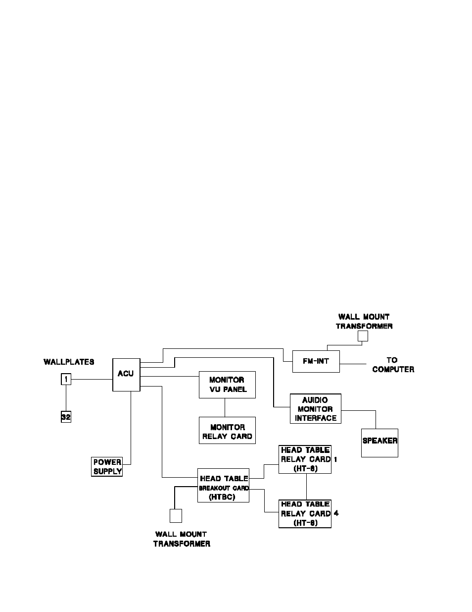
CONTROL WIRING
The following diagram illustrates the control wiring for the ML-116 system. Refer to following
sections for details on head table, page, and facility manager operational hookup diagrams.