Installation, Location of the model 495-001 interface cabinet, Cable and lighting requirements – GAI-Tronics 495-001 Mine Dial / Page Phone Interface Cabinet User Manual
Page 6
Pub. 42004-198D
Model 495-001 Mine Dial/Page Phone Interface Cabinet
Page: 6 of 22
f:\standard ioms - current release\42004 instr. manuals\42004-198d.doc
10/11
Installation
Location of the Model 495-001 Interface Cabinet
The interface cabinet is not rated as “permissible” by MSHA regulations and should be located:
1. Outside the coal mine as close as possible to the point where the cable into the mine emerges from
underground (to avoid, or at least minimize, locating this cable out-of-doors).
2. As close as possible to the center of mine operations and/or point of personnel entry.
3. Within a weather-tight, but ventilated building with a reliable source of 120 V, 60 Hz, ac power (15 A
minimum).
In a mine-shaft installation, the interface cabinet ideally should set on top of the cable installation bore
hole. Typically, it is installed near the elevator shaft or entry slope. If possible, the Model 495-001
Interface Cabinet should be located at the site of the PABX telephone switchboard, but this is not
required. The interface cabinet includes a merge function so that if the PABX telephone switchboard or
the cable between it and the interface cabinet fails, the GAI-Tronics Mine Dial/Page Phone system
automatically switches to an all-stations-merged operation.
Cable and Lighting Requirements
Multiple conductor cable made up of No. AWG 19 twisted pairs with an overall electrostatic shield is
recommended to connect the interface cabinet to distribution points inside the coal mine. This cable is
typically available with 3 to 100 pairs. The larger sizes are used for the initial link from the interface
cabinet into the first main distribution point. The progressively smaller cables can be used for
intermediate and final distribution points.
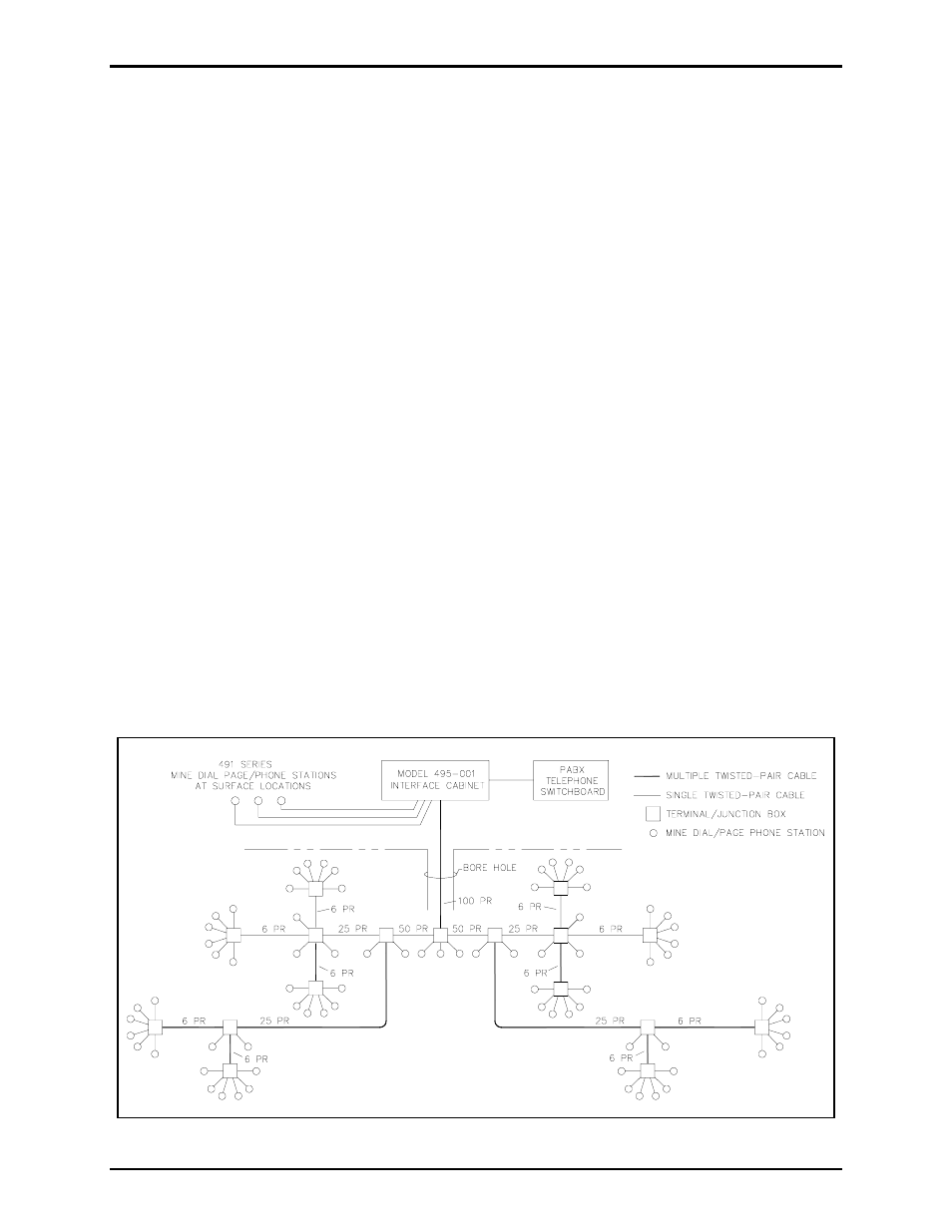
The cable system for a typical 80-station system is shown in Figure 5. The drawing shows the use of 100,
50, 25, and 6-pair cable. Spare conductor pairs in all main distribution cables provide for future
expansion. Cable with an integral messenger wire, commonly called “figure 8 cable,” simplifies
installation.
Figure 5. Typical 80-Station Mine Dial Phone Cable System