Hardware configuration – GAI-Tronics 12599-002 Hot Standby Amplifier Module User Manual
Page 2
Pub. 42004-412A
Model 12599-002 Hot Standby Amplifier Module
Page: 2 of 17
\\s_eng\gtcproddocs\standard ioms - current release\42004 instr. manuals\42004-412a.doc
06/08
Hardware Configuration
The Model 12599-002 Hot Standby Amplifier Module is a printed circuit board assembly (PCBA)
equipped with plug-in type terminal blocks, six high-current relays for switching amplifier outputs, and
12 low-power relays for switching amplifier inputs and providing dry contact status outputs.
The module is also equipped with five slide switches for mode select functions, and six LEDs to indicate
actively switched circuits. Each fault detect input is comprised of a Photo-MOS relay with jumper clips
(J1–J12) to select “wet” or “dry” activation. Each activation type is briefly described below:
Wet Activation – requires an active source voltage of 10–15 V dc from the amplifier when healthy and
removal of the voltage when the amplifier is faulted.
Dry Activation – requires a normally closed (N.C.), dry contact from the amplifier when healthy and
removal of the contact when the amplifier is faulted. This setting is also used when the amplifier has an
open collector fault output, which is actively low (sinking to dc common) when healthy, and floating high
when the amplifier is faulted.
N
OTE
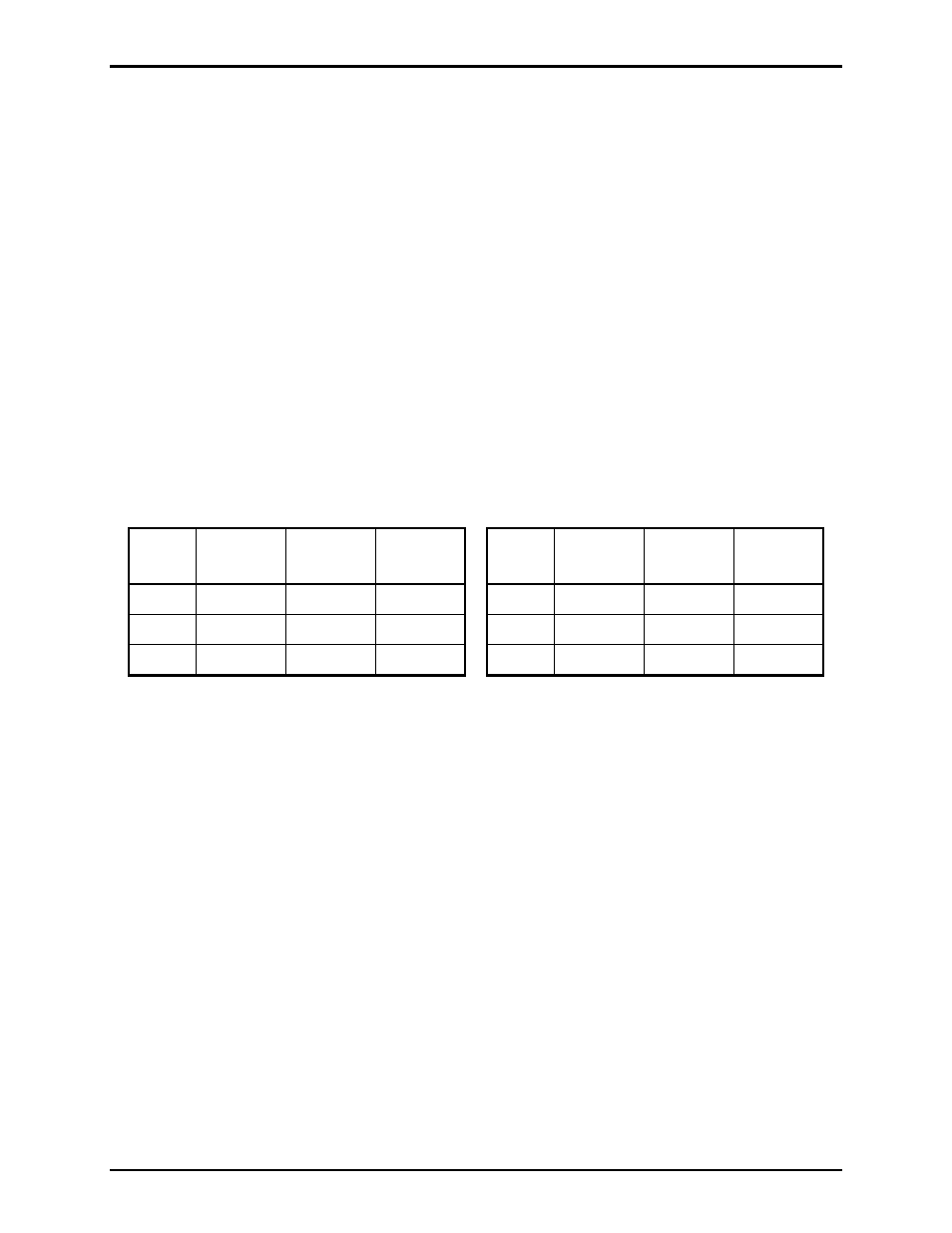
: Jumper clips J1–J12 are set-up in pairs, and each pair must be set to the same position for its
respective input. The following table depicts the corresponding input and jumper pair, and the mode of
operation based on the jumper clip position.
Fault
Input
Jumper
Clips
Wet
Mode
Dry
Mode
Fault
Input
Jumper
Clips
Wet
Mode
Dry
Mode
1
J1 & J2
Pos. 1–2
Pos. 2–3
4
J7 & J8
Pos. 1–2
Pos. 2–3
2
J3 & J4
Pos. 1–2
Pos. 2–3
5
J9 & J10
Pos. 1–2
Pos. 2–3
3
J5 & J6
Pos. 1–2
Pos. 2–3
6
J11 & J12
Pos. 1–2
Pos. 2–3