Mounting the enclosure – GAI-Tronics 370-400 UHF and VHF Page/Party Radio Couplers User Manual
Page 4
Pub. 42004-432D
Model 370-400 UHF and 370-420 VHF Page/Party
®
Radio Couplers
Page:
4 of 13
f:\standard ioms - current release\42004 instr. manuals\42004-432d.doc
11/11
Mounting the Enclosure
1. Mount the enclosure using the four 0.312-
inch (8 mm) diameter holes located on the
mounting flanges with ¼-inch (M6)
hardware. The Page/Party
®
Radio Coupler
is not supplied with conduit or cable
openings.
2. Remove the front panel and drill or punch
entry openings in the rear section of the
enclosure.
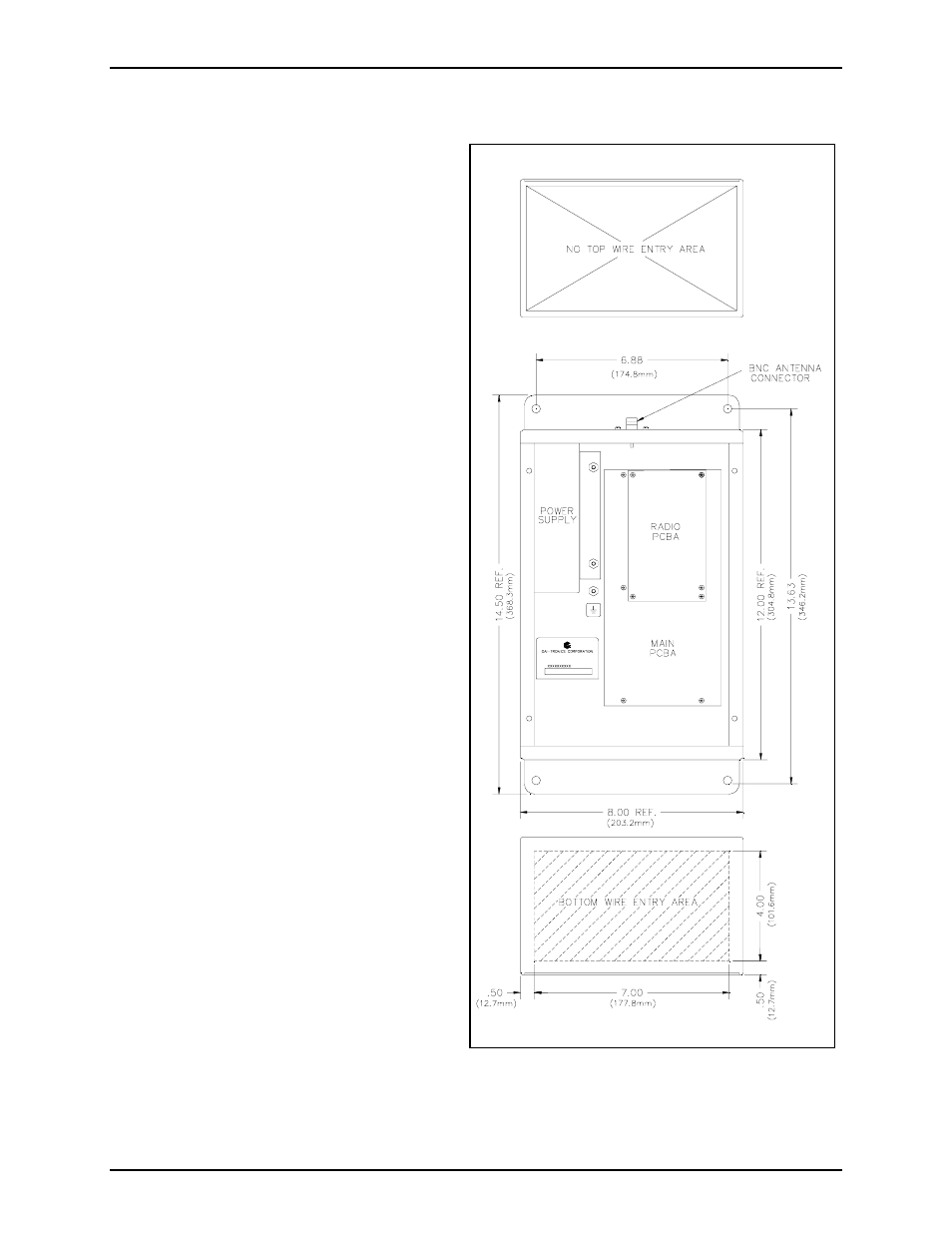
3. Refer to Figure 2 for the suggested
locations. There must be a minimum of ½
inch (13 mm) of material between entry
holes. GAI-Tronics recommends bottom
entry only wherever possible.
The standard orientation shown in Figure 2
locates the power supply housing in the
upper left corner. The orientation of the
enclosure can be rotated 180º to allow clear
access to the top. For specific details
including mounting hole dimensions, refer to
Figure 2. When mounting the enclosure, use
caution to avoid damaging the internal
components.
Figure 2. Mounting Details and Wire Entry Locations